Oil scraper ring

a scraper ring and oil scraper technology, applied in the direction of brake systems, machines/engines, transportation and packaging, etc., can solve the problems of oil being able to overcome the oil scraper ring, the scraping is not very efficient, etc., and achieve the effect of reliable oil scraping

Active Publication Date: 2013-11-21
BURCKHARDT COMPRESSION AG
View PDF9 Cites 4 Cited by
  • Summary
  • Abstract
  • Description
  • Claims
  • Application Information

AI Technical Summary

Benefits of technology

[0006]The oil scraper ring in accordance with the invention is preferably used in connection with an oil scraper ring package, preferably for sealing a horizontally running piston rod. At least two oil scraper rings are arranged lying next to one another in the oil scraper ring package, wherein the long crown parts are arranged above the piston rod, advantageously such that all oil scraper rings are positioned like with respect to the piston rod, wherein the oil scraper rings mutually touch one another. The long crown parts arranged above the piston rod have the effect that oil scraped from the piston rod by the oil scraper rings cannot escape upwardly from the oil scraper ring package and thus can only escape following the gravitational force downwardly and possibly laterally. This embodiment has the advantage that the oil can generally be scraped better from the piston rod and / or has the advantage that less oil can overcome the oil scraper ring package.
[0008]The oil scraper ring in accordance with the invention has the advantage that this enables a substantial and efficient scraping of the oil present at the piston rod and that the oil scraper ring only has a small wear. In an advantageous embodiment the oil scraper ring in accordance with the invention comprises a scraper which has a larger hardness than the material of the holding ring which forms the first end face and which is determined for abutment at the piston rod. Such a scraper has a stable and, preferably also sharp, scraping edge which ensures an efficient scraping of the oil. Moreover, the oil scraper ring in accordance with the invention comprises a holding ring which has a first end face formed of plastic which is oriented towards the piston rod and which is determined for the contact at the piston rod. The oil scraper ring in accordance with the invention is configured in an advantageous embodiment such that both the first end face and also the scraping edge can simultaneously lie at the piston rod which has the consequence that the scraping edge only contacts at the piston rod with very little pressure or even no pressure, since a part of the, in particularly radially inwardly acting forces, are transferred via the first end face. The scraping edge thereby experiences a very small wear. Moreover, the position and orientation of the scraping edge is stabilized with respect to the piston rod, by the end face of the holding ring lying at the piston rod, and, in particular is stabilized also with respect to any arising movement. In a particularly advantageous embodiment the material forming the first end face is composed of a plastic with very good dry running properties, such as a filled PTFE or a high temperature polymer modified with filling materials suitable for dry running, such as PTFE, MoS2, graphite etc. The scraper or the complete oil scraper ring, with or without scraper, is preferably composed of a metal, such as grey cast, bronze and aluminum or of a plastic, in particular of a high temperature polymer such as PEEK, polyimide or PPS.

Problems solved by technology

This known oil scraper ring has the disadvantage that the scraping is not very efficient and / or that the oil can overcome the oil scraper ring.

Method used


Image

  • Oil scraper ring
  • Oil scraper ring
  • Oil scraper ring

Examples


Embodiment Construction

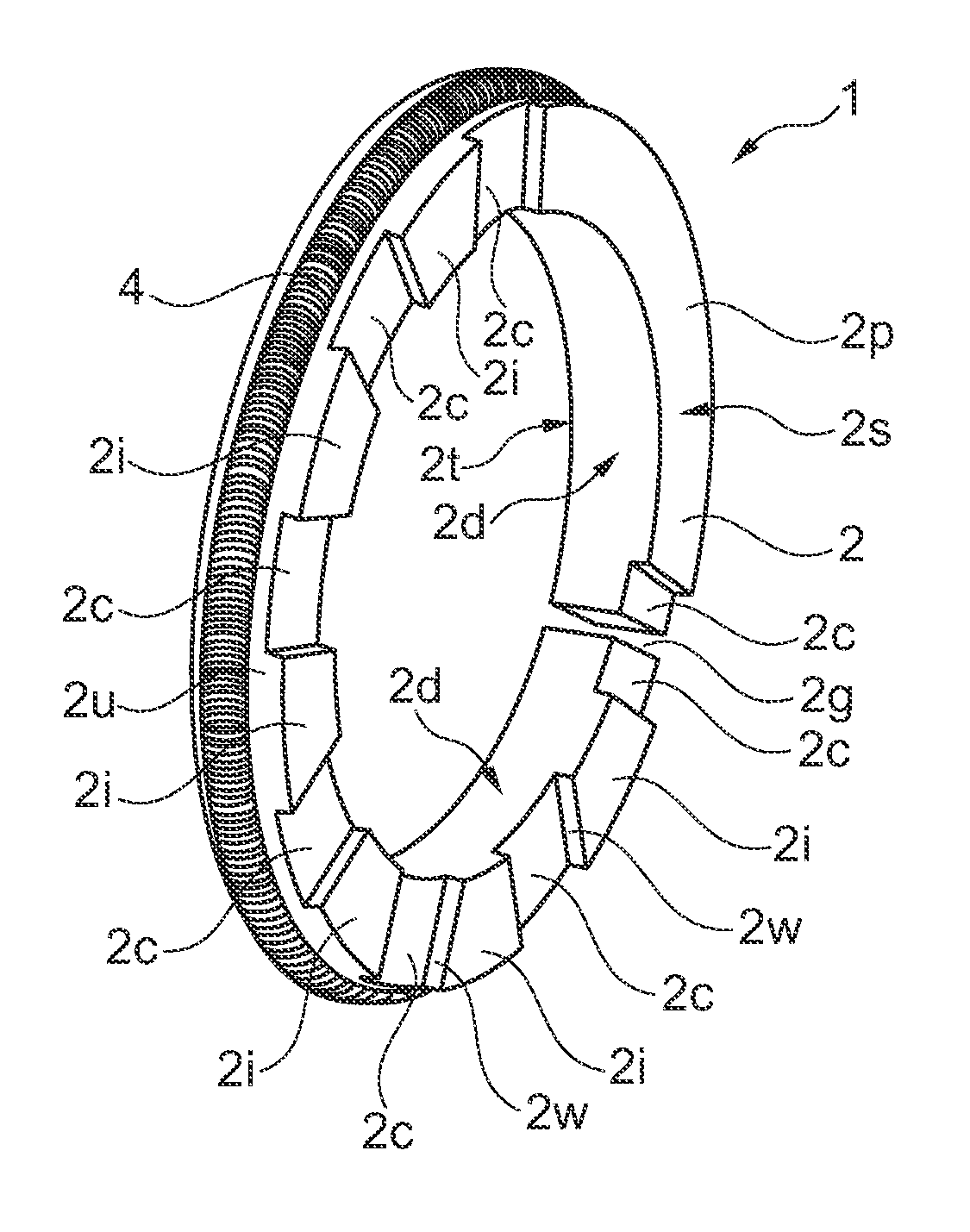
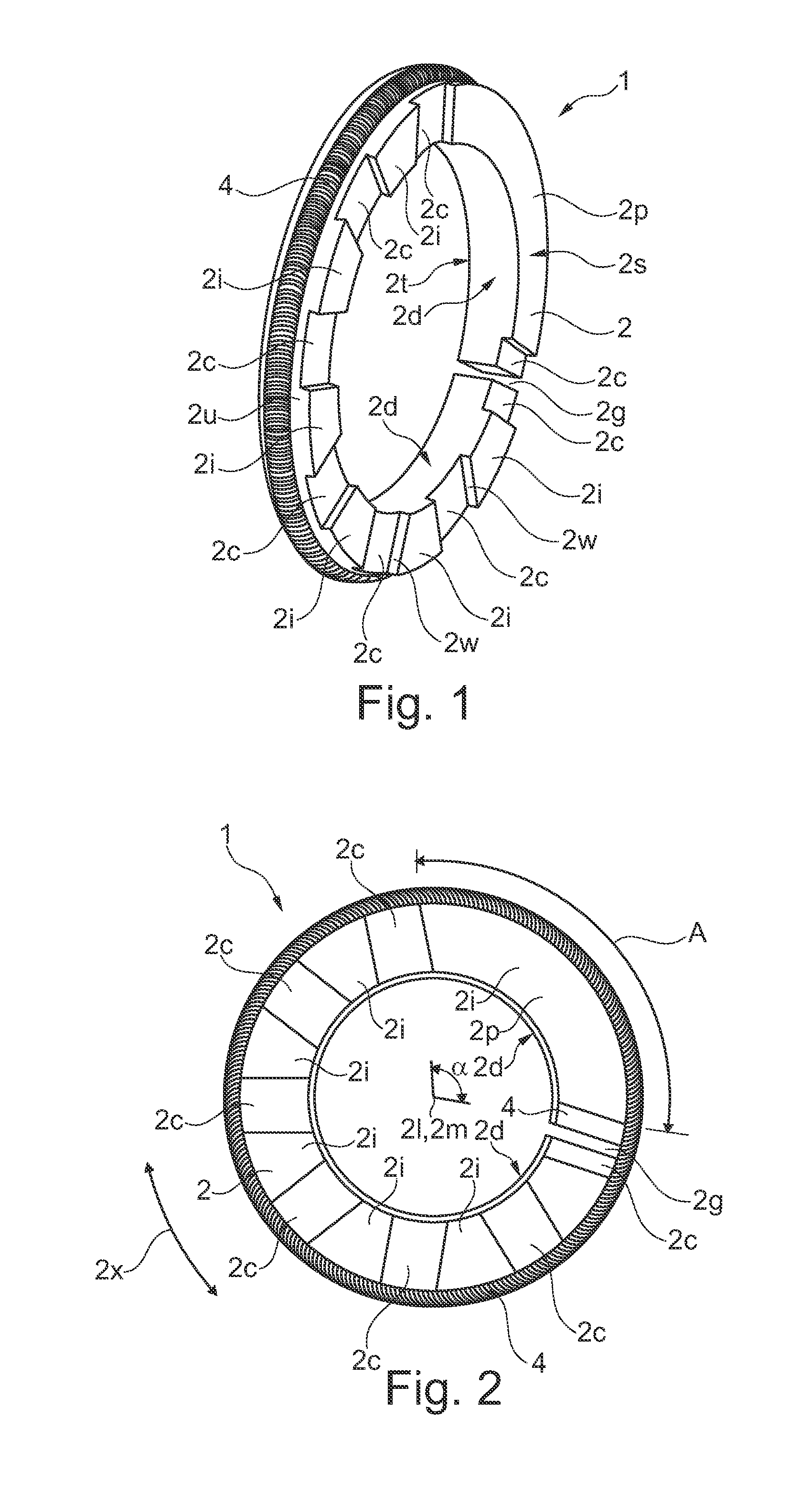
[0034]FIG. 1 in a perspective view and FIG. 2 in a top view show an oil scraper ring 2 which extends in a circumferential direction 2x about a center 2l and which has a longitudinal axis 2m extending through the center 2l, wherein the oil scraper ring 2 has an end face 2d orientated towards the center 2l, and wherein the oil scraper ring 2 has a first side surface 2s, a second side surface 2t, as well as an outer surface 2u facing away with respect to the center 2l. The oil scraper ring 2 has a plurality of passages 2c extending towards the center 2l at the first side surface 2s which passages are mutually spaced apart in the circumferential direction 2x and which passages extend in the radial direction over the complete width of the first side surface 2s and thereby form a fluid conducting connection between the end face 2d and the outer surfaces 2u. A crown part 2i is arranged extending in the circumferential direction between two passages 2c, wherein the crown part 2i respectivel...


PUM


Abstract

The oil control ring (2) extends in a circumferential direction (2x) about a center (2l) and has a longitudinal axis (2m) that passes through the center (2l), wherein the oil control ring (2) has an end face (2d) that faces the center (2l), and wherein the oil control ring (2) has a first lateral surface (2s), a second lateral surface (2t), and an outer surface (2u) facing away from the center (2l), wherein the oil control ring (2) has a plurality of channels (2c) extending toward the center (2l) on the first lateral surface (2s), said channels being arranged at mutual distances in the circumferential direction (2x) and extending over the entire width of the first lateral surface (2s) in the radial direction and thereby forming a fluid-conducting connection between the end face (2d) and the outer surface (2u), and wherein crown parts (2i) extending in the circumferential direction (2x) are arranged between pairs of channels (2c), wherein each crown part (2i) protrudes beyond the respective channel (2c) in the direction of extent of the longitudinal axis (2m) and forms a lateral channel surface (2w) for the channel (2c), wherein at least one of the crown parts (5i) is designed as a long crown part (2p) and extends over an angular range (a) between 60 degrees and 350 degrees in the circumferential direction (2x). 212×2121.

Description

[0001]The invention relates to an oil scraper ring in accordance with the preamble of claim 1.BACKGROUND OF THE INVENTION[0002]The document EP 1 446 597 B1 discloses an oil scraper ring which can, in particular be used as an oil barrier for piston rods of ship diesel engines. The oil scraper ring has oil scraper lips composed of plastic oriented towards the piston rod side which oil scraper lips scrape the oil present at the piston rod and, for example, supply this again to a crank housing. This known oil scraper ring has the disadvantage that the scraping is not very efficient and / or that the oil can overcome the oil scraper ring.SUMMARY OF THE INVENTION[0003]It is the object of the invention to form an advantageous oil scraper ring which ensures a reliable oil scraping during a long period of operation. The object is satisfied by an oil scraper ring having the features of claim 1. The subordinate claims 2 to 13 relate to further advantageous embodiments. The object is further sati...

Claims


Application Information

Patent Timeline
Patent Type & Authority Applications(United States)
IPC IPC(8): F16J9/20
CPCF16J9/203F16J9/062F16J15/26F16J15/32F16J15/3212F16J15/3208F16J15/3272F02F5/00
Inventor FEISTEL, NORBERT
Owner BURCKHARDT COMPRESSION AG
Why Eureka
Try Eureka