Loop antenna with switchable feeding and grounding points

a loop antenna and switching point technology, applied in the field of wireless communication, can solve the problems of reducing the cellular network, requiring more system resources, and under-performing devices, and achieve the effect of limiting the performance drop

Active Publication Date: 2013-11-21
KYOCERA AVX COMPONENTS (SAN DIEGO) INC
View PDF1 Cites 40 Cited by
  • Summary
  • Abstract
  • Description
  • Claims
  • Application Information

AI Technical Summary

Benefits of technology

[0014]For the same reason, performances differences can also be of several dB if the device is held in the right hand (FHR) or in the left hand. Leveraging on the almost s

Problems solved by technology

Under-performing mobile devices in regard to the radiated performance of the device will degrade the cellular network, with these under-performing devices requiring more system resources compared to more efficient mobile devices.
Though various antenna techniques and topologies have been proposed and developed to improve antenna efficiency for internal applications, they all suffer from the limitation of being optimized for a single use case such as device in user's hand, device against the user's head, or device in free space environment.
A symmetrical radiator design is required to generate the symmetrical coupling, which can be achieved during the

Method used


Image

  • Loop antenna with switchable feeding and grounding points
  • Loop antenna with switchable feeding and grounding points
  • Loop antenna with switchable feeding and grounding points

Examples


Embodiment Construction

[0034]In the following description, for purposes of explanation and not limitation, details and descriptions are set forth in order to provide a thorough understanding of the present invention. However, it will be apparent to those skilled in the art that the present invention may be practiced in other embodiments that depart from these details and descriptions.

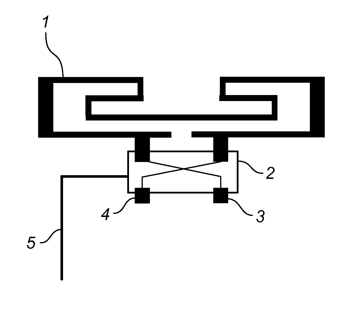
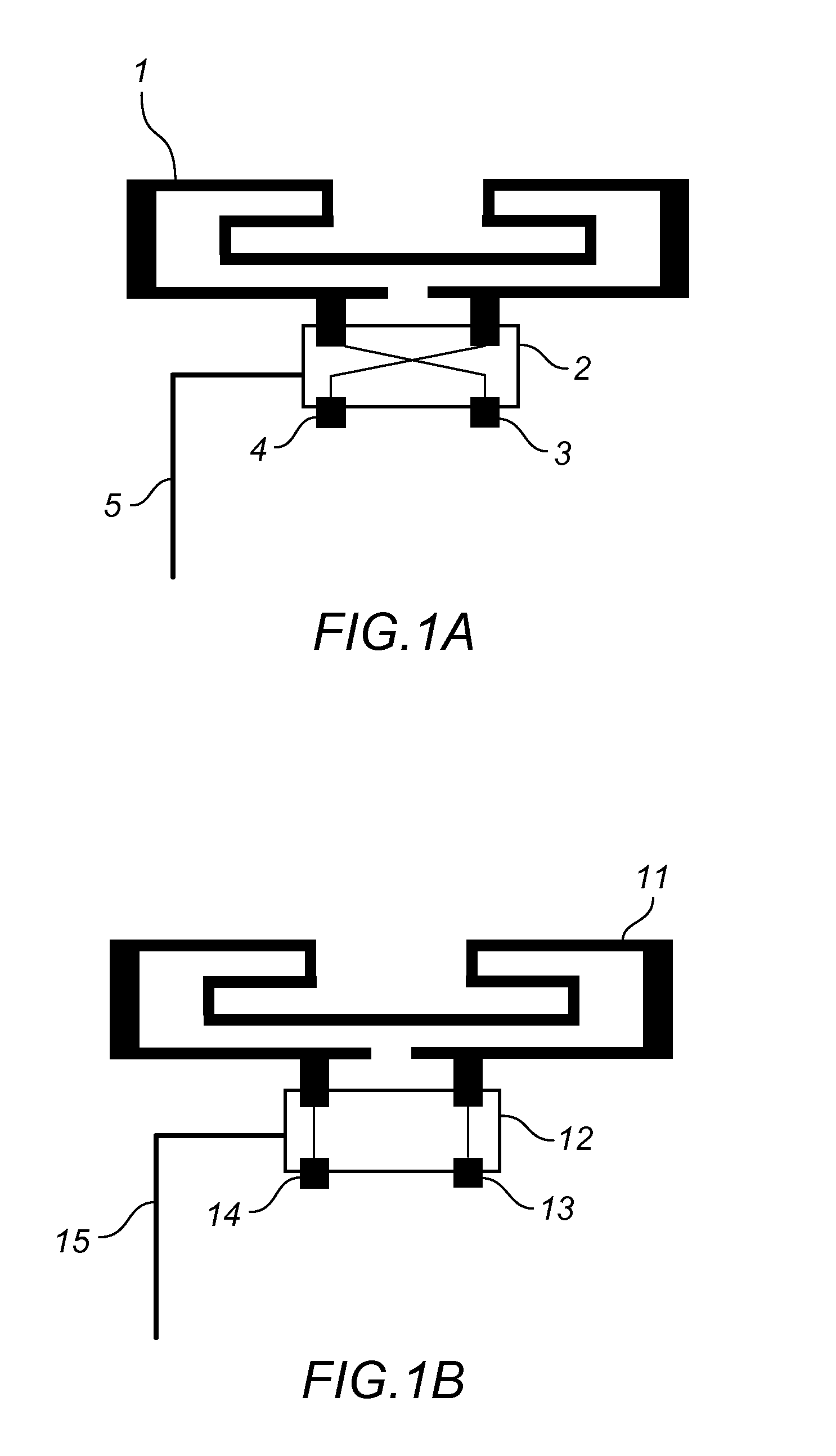
[0035]According to an example embodiment, the active swapping circuit can comprise transistors, diodes or Micro Electrical Mechanical System (MEMS) devices.

[0036]In another embodiment, the swapping circuit can have more than two inputs and two outputs and can offer a larger matrix of output connection for the radiator's connection points.

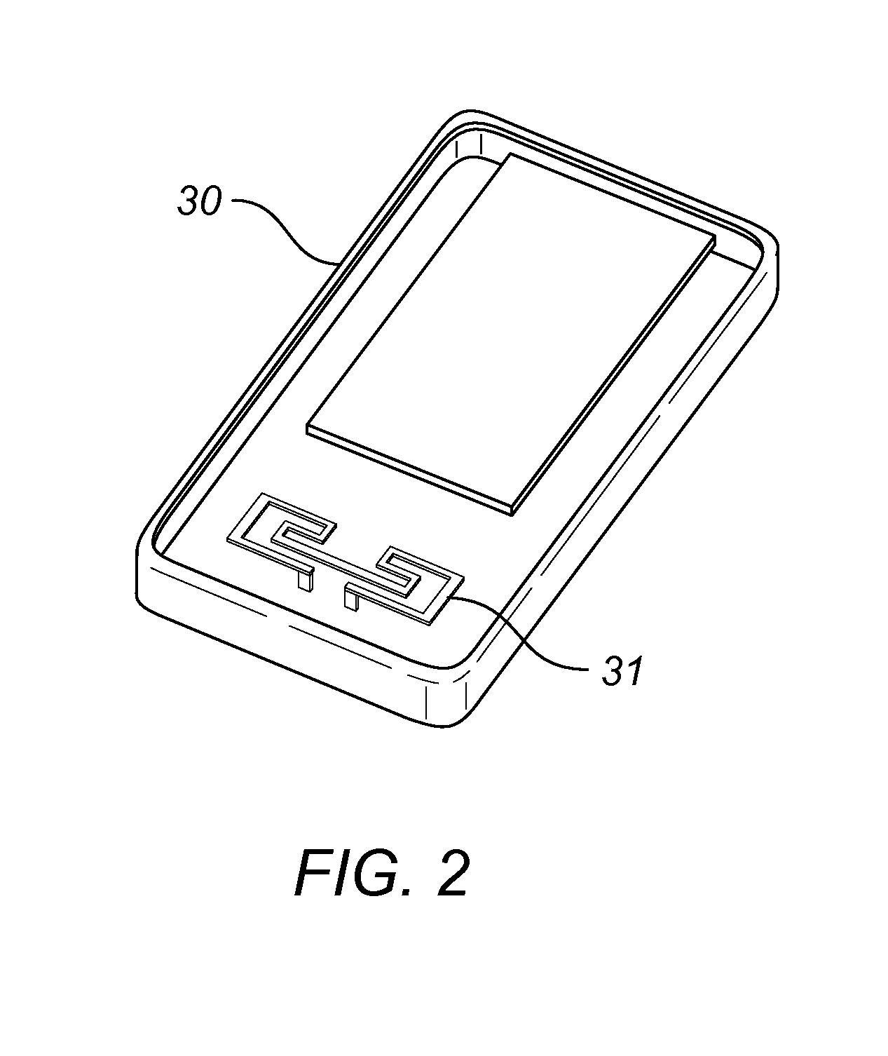
[0037]In another embodiment of the invention, a parasitic element can be coupled to a portion of the folded loop antenna. An active component can be connected to or coupled to the parasitic element, with this active component being used to alter the impedance loading on the parasitic element....


PUM


Abstract

An active differential antenna is described that provides for improved performance for wireless communication systems across a wide set of use cases and environments. A balanced antenna structure along with switch assembly provides the differential mode radiation which results in minimal coupling to the components and items in the near field of the antenna. This results in an efficient antenna that is well isolated from the local environment of the antenna. The switch assembly is configured to switch the feed and ground connections of the differential design when needed to provide similar antenna performance for both “against head left” and “against head right” use cases for a cellular handset application for example. An active component or circuit can be integrated or coupled to the antenna design to provide the capability to dynamically balance the antenna to maintain pattern symmetry and efficiency.

Description

CROSS-REFERENCE TO RELATED APPLICATIONS[0001]This application claims benefit of priority with U.S. Provisional Ser. No. 61 / 636,553, filed Apr. 20, 2012, titled “LOOP ANTENNA WITH SWITCHABLE FEEDING AND GROUNDING POINTS”; the contents of which are hereby incorporated by reference.BACKGROUND OF THE INVENTION[0002]1. Field of the Invention[0003]The present invention relates generally to the field of wireless communication. In particular, this invention relates to an active differential mode loop antenna configured to maintain efficient operation across a wide set of use cases for use in wireless communications.[0004]2. Description of the Related Art[0005]The availability of wireless services, such as Global System for Mobile Communications (GSM), Radio Frequency Identification (RFID), Distributed Control System (DCS), Personal Communications Service (PCS), UW, Digital Video Broadcasting-Terrestrial / Handheld (DVB-T / H), Wireless Fidelity (Wifi), Bt, Worldwide Interoperability for Microwa...

Claims


Application Information

Patent Timeline
IPC IPC(8): H01Q7/00
CPCH01Q7/00H01Q1/243H01Q5/307H01Q21/28
Inventor PAJONA, OLIVIERDESCLOS, LAURENT
Owner KYOCERA AVX COMPONENTS (SAN DIEGO) INC
Why Eureka
Try Eureka