Radiation generating target, radiation generating tube, radiation generating apparatus, and radiation imaging system

a radiation generating tube and radiation generating technology, applied in the direction of x-ray tube target materials, instruments, x-ray tube targets and convertors, etc., can solve the problems of radiation dose reduction, exfoliation or cracking,

Inactive Publication Date: 2013-11-21
CANON KK
View PDF54 Cites 32 Cited by
  • Summary
  • Abstract
  • Description
  • Claims
  • Application Information

AI Technical Summary

Problems solved by technology

When the exfoliation or the crack of the target has occurred, there is a possibility that the target melts while starting melting from the portion of the exfoliation or the crack, and the dose of the radi...

Method used


Image

  • Radiation generating target, radiation generating tube, radiation generating apparatus, and radiation imaging system
  • Radiation generating target, radiation generating tube, radiation generating apparatus, and radiation imaging system
  • Radiation generating target, radiation generating tube, radiation generating apparatus, and radiation imaging system

Examples


example 1

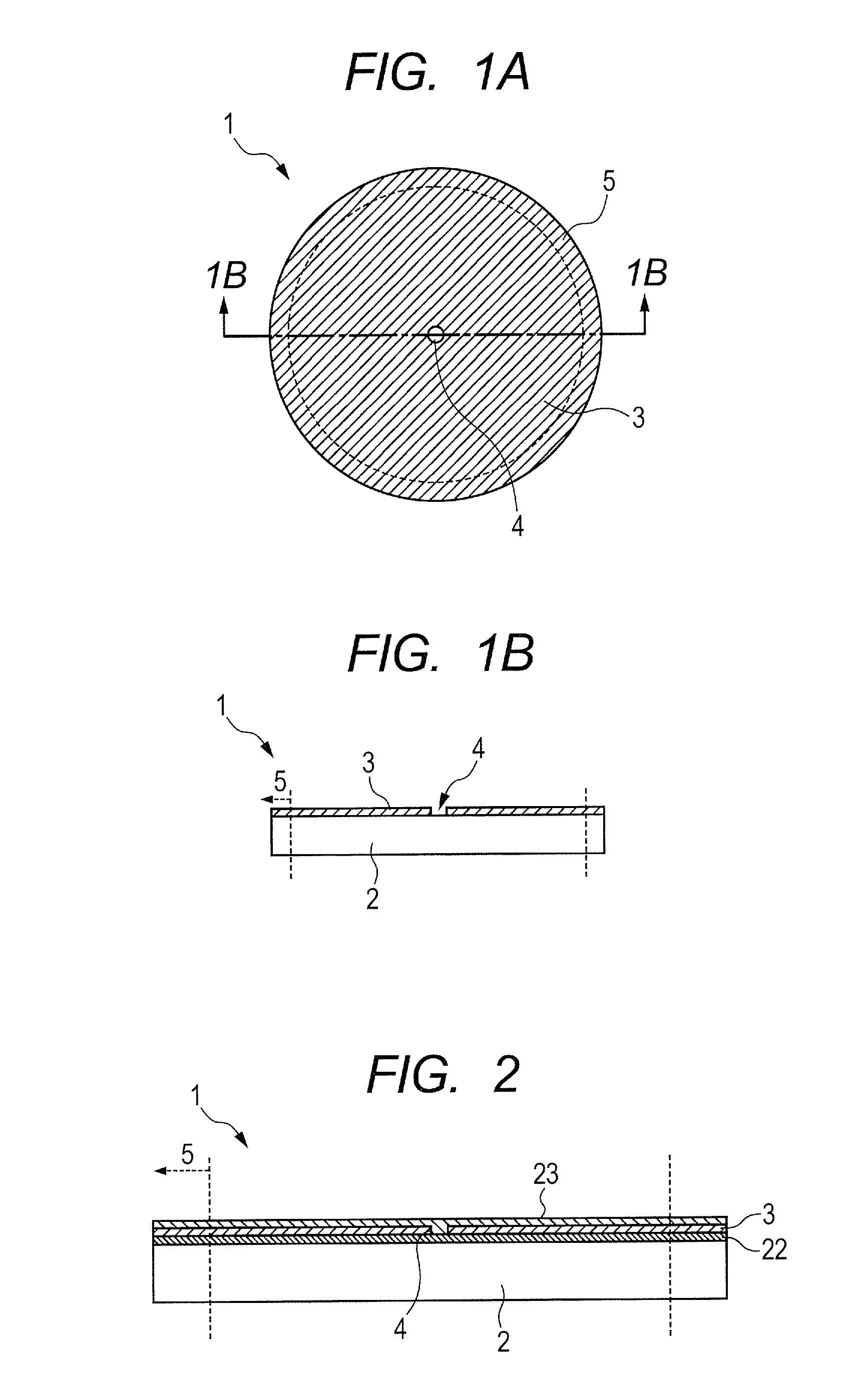
[0050]A radiation transmission type target 1 illustrated in FIG. 1A and FIG. 1B was produced. In FIG. 1A and FIG. 1B, a target 1, a supporting substrate 2, a target layer 3, an opening 4, and a portion to be bonded 5 for fixing the target 1 to an anode are shown.

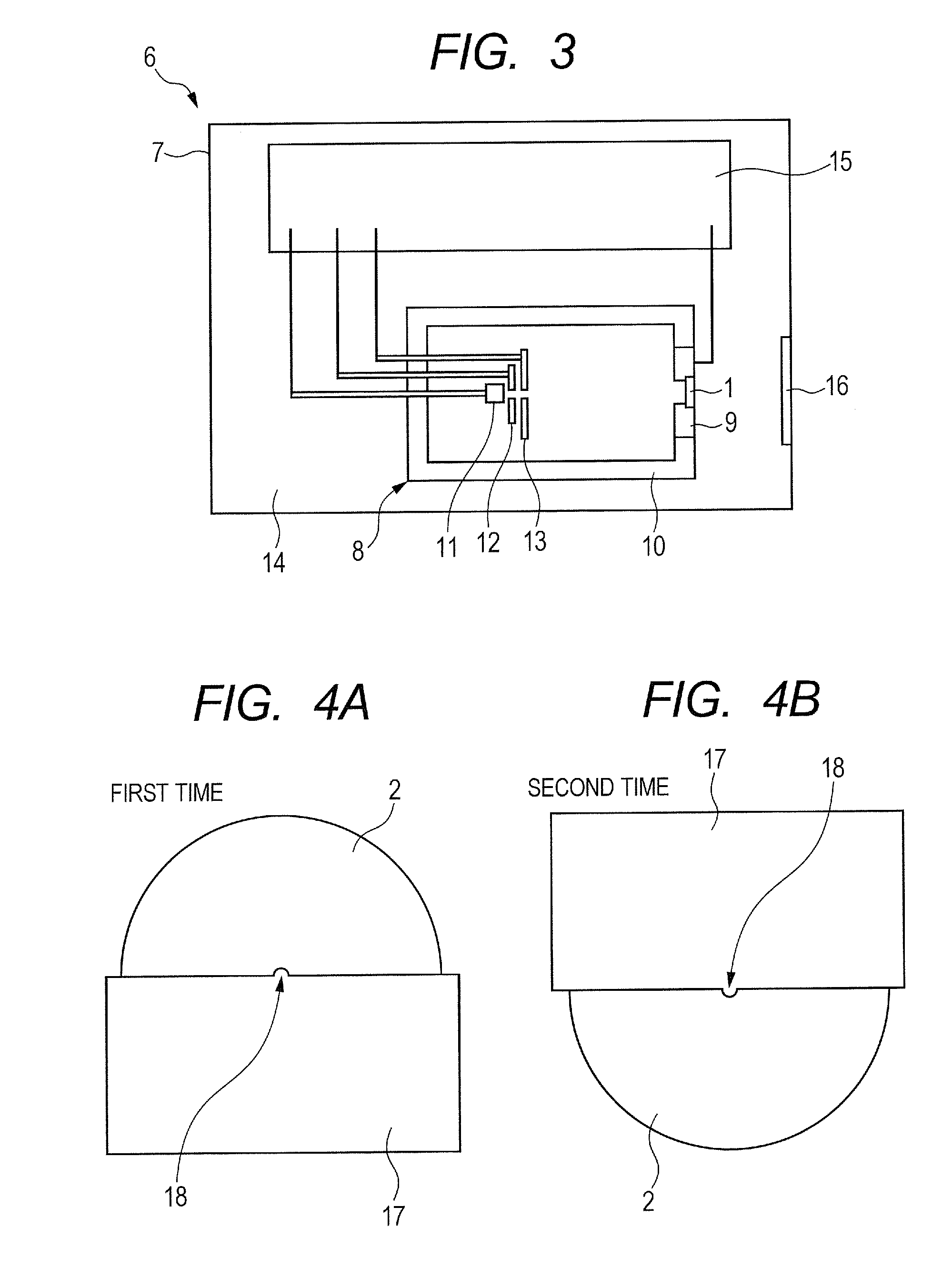
[0051]The supporting substrate 2 was formed from diamond with a diameter of 5 mm and a thickness of 1 mm, and tungsten as the target layer 3 was film-formed on the supporting substrate 2 so as to become 10 μm thick with a sputtering process. The sputtering process was conducted twice separately while using a metal mask 17 illustrated in FIG. 4A and FIG. 4B, regarding the projecting portion 18 of the metal mask 17 as the center, and changing the position by 180 degrees around the projecting portion 18. Then, the opening 4 having no tungsten film-formed therein was formed in a region which overlapped with the projecting portion 18, and the target 1 was produced. The opening 4 was formed into a circle shape with a diameter of 0...

example 2

[0057]The radiation generating target of the present example is different from Example 1 in the form of the opening 4. A supporting substrate 2 was formed from diamond with a diameter of 5 mm and a thickness of 1 mm, and tungsten as the target layer 3 was film-formed on the supporting substrate 2 so as to become 10 μm thick with a sputtering process. The sputtering process was conducted with the use of a metal mask 19 illustrated in FIG. 5A and FIG. 5B, thereby the opening 4 was formed, and the target 1 was produced. The metal mask 19 has a cross arm portion 20 which has an intersection in a desired portion, and a rectangular columnar contact portion 21 for masking the supporting substrate 2, which projects in the intersection. This metal mask 19 is set in such a state that the contact portion faces to the supporting substrate 2 side and the tip of the contact portion is brought into contact with the supporting substrate 2. In a state in which the metal mask 19 is set, the region of...


PUM


Abstract

The present invention provides a transmission type radiation generating target which can suppress the exfoliation or the crack of a target layer in an interface between a supporting substrate and the target layer, even when the density of incident electrons has been enhanced or the potential of the target has been enhanced. The transmission type radiation generating target includes a supporting substrate, and a target layer which is arranged on the supporting substrate and generates radiation in response to irradiation with an electron beam, wherein the target layer has an opening through which the supporting substrate is exposed, and the opening overlaps with a position at which the density of the irradiation with the electron beam is maximum.

Description

BACKGROUND OF THE INVENTION[0001]1. Field of the Invention[0002]The present invention relates to a radiation generating target which can be applied to non-destructive X-ray imaging and the like in a medical equipment field and an industrial equipment field, and to a radiation generating tube, a radiation generating apparatus and a radiation imaging system, which are provided with the radiation generating target.[0003]2. Description of the Related Art[0004]Generally, a radiation generating apparatus accelerates electrons to be emitted from an electron source by high voltage, and makes the accelerated electrons irradiate a target formed from a metal such as tungsten to make the target generate radiation such as X-rays. The target which generates the radiation includes a reflecting type target from which a radiation having reflected on the surface of the target is taken out, and a transmitting type target from which a radiation having permeated through the target is taken out. When an ...

Claims


Application Information

Patent Timeline
IPC IPC(8): H01J35/08G01N23/04
CPCH01J35/08G01N23/04H01J2235/084H01J35/116H01J2235/08H01J2235/081H01J2235/083H01J2235/088
Inventor YAMAZAKI, KOJITAMURA, MIKI
Owner CANON KK
Why Eureka
Try Eureka