Radiation image detector and phase contrast radiation imaging apparatus

a radiation image detector and imaging apparatus technology, applied in imaging devices, instruments, nuclear engineering, etc., can solve the problems of difficult to produce uniform diffraction gratings, and achieve the effect of simple structure and easy manufacturing

Inactive Publication Date: 2009-04-30
FUJIFILM CORP
View PDF2 Cites 52 Cited by
  • Summary
  • Abstract
  • Description
  • Claims
  • Application Information

AI Technical Summary

Benefits of technology

[0010]The present invention has been developed in view of the foregoing circumstances. It is an object of the present invention to provide a phase contrast radiation imaging apparatus having a simpler

Problems solved by technology

It is necessary to provide two diffraction gratings of sizes equivalent to that of a subject in the X ray imaging apparatus disclosed in U.S. Pat. No. 7,180,979, which is costly.
It is necessary to employ a special manufac

Method used


Image

  • Radiation image detector and phase contrast radiation imaging apparatus
  • Radiation image detector and phase contrast radiation imaging apparatus
  • Radiation image detector and phase contrast radiation imaging apparatus

Examples


first embodiment

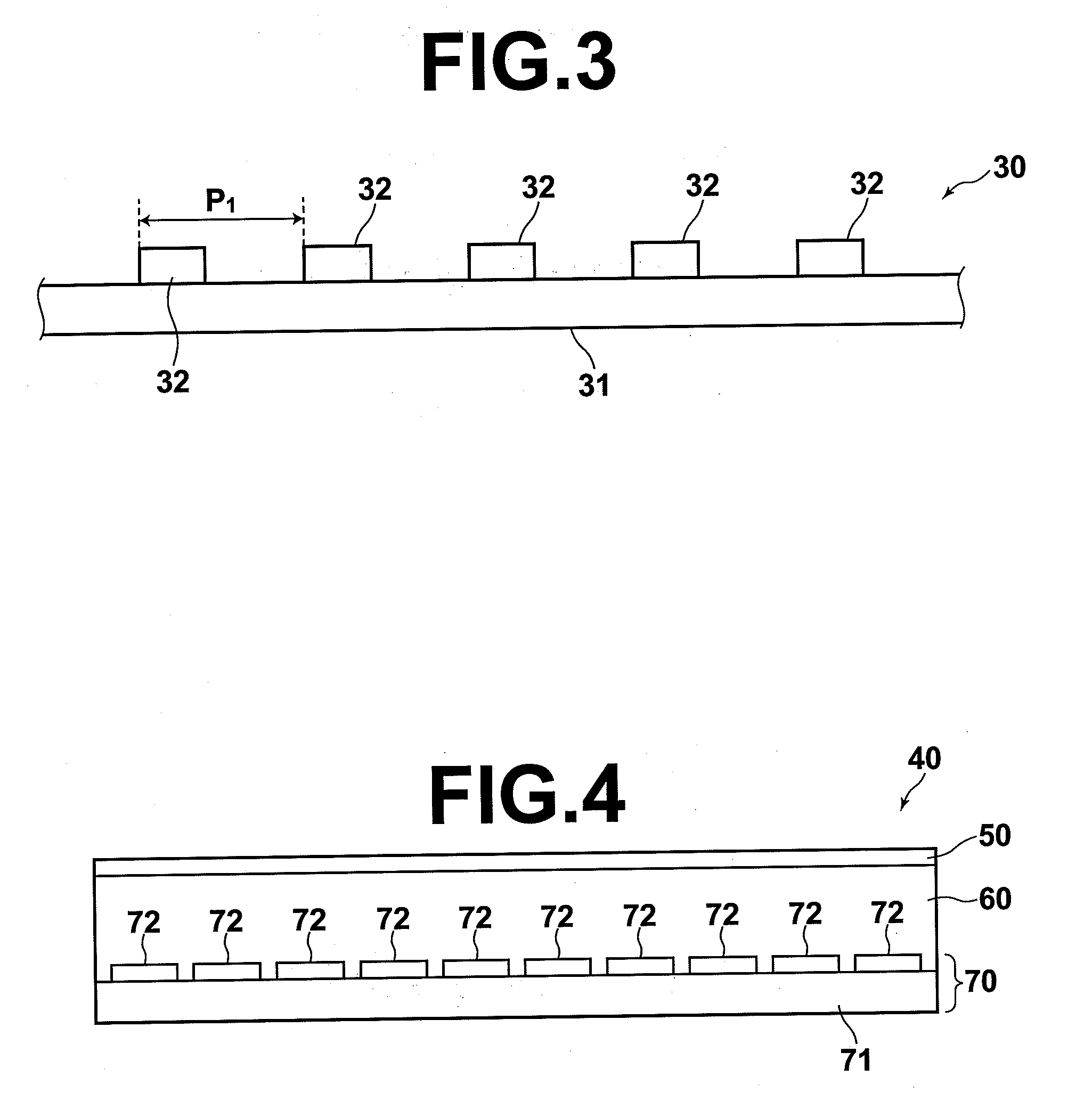
[0088]As illustrated in FIG. 3, the diffraction grating 30 is equipped with a substrate 31, and a plurality of diffraction members 32 which are attached to the substrate 31. The substrate 31 may be formed by glass, for example. All of the plurality of diffraction members 32 are linear, and extend unidirectionally (the direction perpendicular to the drawing sheet of FIG. 3). The pitch P1 at which the diffraction members 32 are provided is constant in the

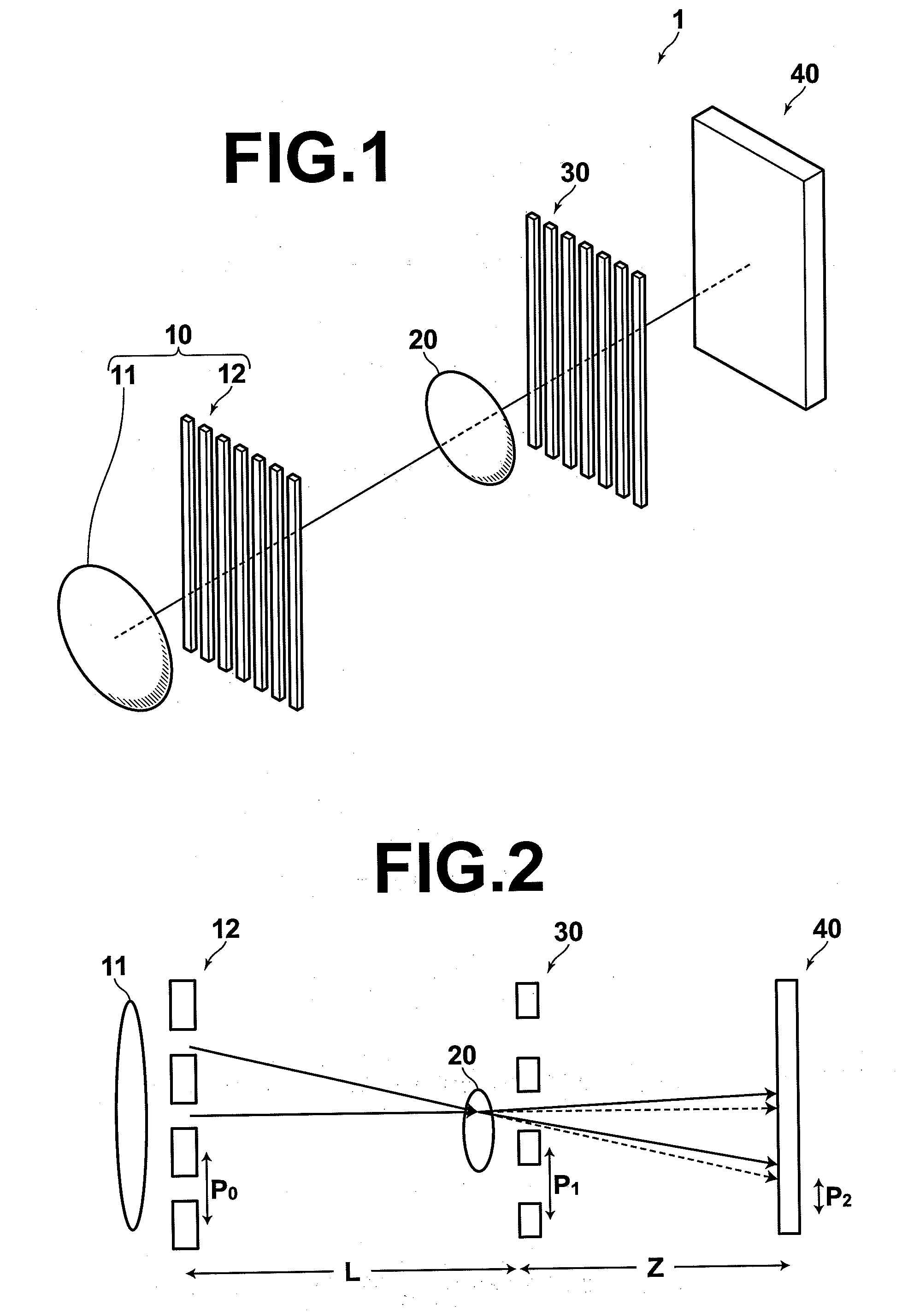
[0089]The phase contrast radiation imaging apparatus of the first embodiment obtains phase contrast radiation data of the subject, utilizing the Talbot effect which is generated at the diffraction grating 30. For this to occur, the placement of the diffraction grating 30 and the pitch P1 (that is, the period of the diffraction grating) at which the diffraction members 32 are provided must be set to satisfy the following equation:

Z=(m+½)P12 / λ

Here, m is either 0 or a positive integer, and λ is the wavelength of the radiation.

[0090]Gold,...

second embodiment

[0138]As illustrated in FIGS. 18A, 18B, and 18C, the radiation image detector 200 of the phase contrast radiation imaging apparatus of the second embodiment is formed by: a first electrode layer 201 that transmits radiation; a recording photoconductive layer 202 that generates electric charges when irradiated by radiation which has passed through the first electrode layer 201; a charge transport layer 204 that functions as an insulator with respect to electric charges of one of the polarities from between the charge pairs generated within the recording photoconductive layer 202, and functions as a conductor with respect electric charges of the other polarity; a readout photoconductive layer 205 that generates electric charges when irradiated by readout light; and a second electrode layer 206, which are laminated in this order. A charge accumulating section 203, at which electric charges which are generated within the recording photoconductive layer 202 are accumulated, is formed at ...

third embodiment

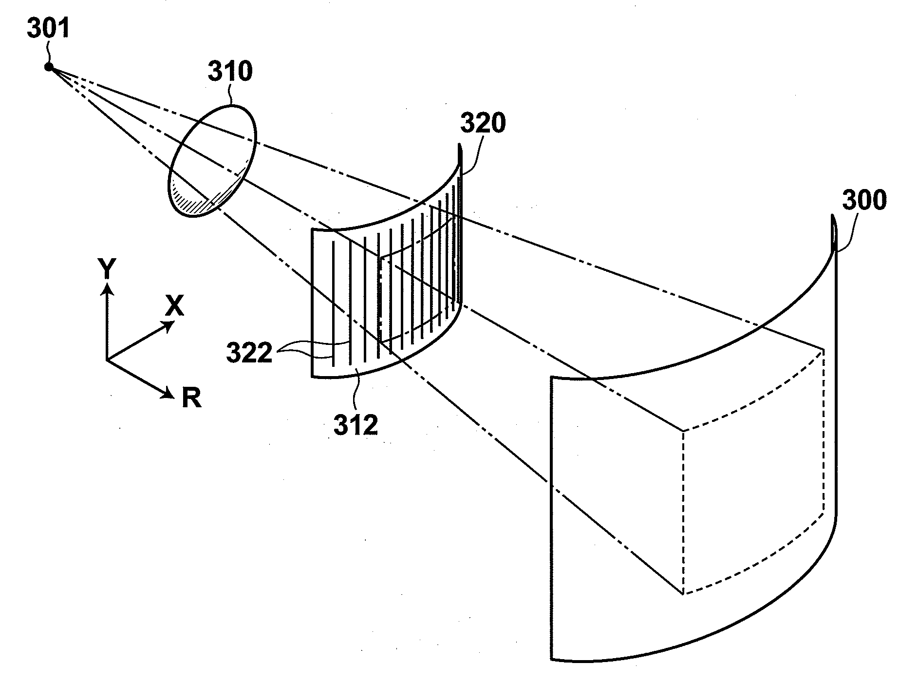
[0163]As illustrated in FIG. 22, the phase contrast radiation imaging apparatus of the third embodiment is equipped with: a radiation source 301 that emits radiation toward a subject 10; a diffraction grating 320, onto which the radiation emitted from the radiation source 301 is irradiated, and which is configured to generate the Talbot effect when irradiated by the radiation; and a radiation image detector 300 that detects the radiation, which is diffracted by the diffraction grating 320.

[0164]The radiation source 301 has spatial interference properties that cause the Talbot effect to occur when it emits radiation onto the diffraction grating 320. For example, if the size of the light emitting spot (that is, the diameter of the aperture of the radiation source) is approximately 30 microns, the spatial interference properties approximately five meters away or greater from the radiation source are those that cause the Talbot effect. A micro focus X ray tube or a plasma X ray source m...


PUM


Abstract

A phase contrast radiation imaging apparatus is includes a radiation source, a diffraction grating, and a radiation image detector. The radiation image detector is equipped with a charge generating layer that generates electric charges when irradiated with radiation, and charge collecting electrodes that collect the electric charges. The charge collecting electrodes are linear electrode groups, constituted by linear electrodes which are arranged at a constant period and are electrically connected to each other, provided to have different phases from each other. Thereby, use of a conventional amplitude diffraction grating is obviated.

Description

BACKGROUND OF THE INVENTION[0001]1. Field of the Invention[0002]The present invention relates to a phase contrast radiation imaging apparatus and a phase contrast radiation imaging method that utilize a Talbot interferometer, and a radiation image detector which is employed by the phase contrast radiation imaging apparatus.[0003]2. Description of the Related Art[0004]The application of Talbot interferometers, in which the Talbot effect is generated by a diffraction grating and another diffraction grating is used to generate Moire fringes, to the field of X ray imaging is being investigated (refer to U.S. Pat. Nos. 5,812,629 and 7,180,979, for example).[0005]U.S. Pat. No. 7,180,979 discloses an X ray imaging apparatus that utilizes a Talbot interferometer constituted by an X ray source, two diffraction gratings, and an X ray image detector.[0006]Japanese Unexamined Patent Publication No. 2006-259264 discloses production of an amplitude diffraction grating by forming deep grooves in r...

Claims


Application Information

Patent Timeline
IPC IPC(8): G01N23/04
CPCG01T1/2928A61B6/484G01T1/241G21K2207/005
Inventor TAKAHASHI, KENJIOKADA, YOSHIHIRO
Owner FUJIFILM CORP
Why Eureka
Try Eureka