Radiation imaging system and driving method thereof

a technology of radiation imaging and driving method, which is applied in the direction of material analysis by transmitting radiation, instruments, electrical apparatuses, etc., can solve the problems of shortening the read time, small noise in the addition of analogue signals, and high s/n, so as to shorten the read time, and increase the number of pixels

Inactive Publication Date: 2009-01-13
CANON KK
View PDF28 Cites 50 Cited by
  • Summary
  • Abstract
  • Description
  • Claims
  • Application Information

AI Technical Summary

Benefits of technology

[0010]A technique for the pixel addition is variously considered. For example, this includes a technique in which two pieces of gate wiring are turned on at the same time, and as shown in FIG. 11, an analogue signal is subjected to the pixel addition before the AD conversion of an AD converter, and a technique in which, as shown in FIG. 12, the digital signal is added after the AD conversion. In the case of the former, since the analogue signal is added, and after that, the A / D conversion is performed, the data amount for the AD conversion is reduced, and the read time can be shortened. In contrast to this, in the case of the later, since the analogue signals are all AD-converted into digital signals, and then, the digital signals are added, the read time takes long. Further, as compared to the addition of the digital signals, the addition of the analogue signals is small in noise and high in S / N.
[0017]Hence, the pixel addition is quick in frame rate, and the pixel addition having an analogue signal high in S / N is generally performed. Further, the pixel addition can perform radiographing by changing the number of pixels by the addition of a total of four pixels (hereinafter, two×two pixels addition) of two pixels in the direction to the gate wiring and two pixels in the direction to the signal wiring and a total of nine pixels of three pixels in the direction to the gate wiring and three pixels in the direction to the signal wiring.
[0018]More increased the number of pixels is, more shorter the read time becomes, and the frame rate and the S / N are improved, whereas the resolution is deteriorated since a plurality of pixels is put together into one pixel and output as one pixel (plural pixels). Hence, in view of the frame rate, S / N, and resolving power, the engineer who performs the radiographing selects the pixels according to the state of the object.
[0027]The present invention has been carried out in view of the above described problem, and an object of the invention is to provide a radiation imaging apparatus that realizes acquisition of an object image having a high quality and no artifact when performing a gain correction for the radiographed object image.

Problems solved by technology

When a moving image is radiographed by using the radiation imaging apparatus, as compared to the still image, the shortening of read time (quickening a frame rate) and the improvement of a S / N cause a problem.
Further, as compared to the addition of the digital signals, the addition of the analogue signals is small in noise and high in S / N.

Method used


Image

  • Radiation imaging system and driving method thereof
  • Radiation imaging system and driving method thereof
  • Radiation imaging system and driving method thereof

Examples


first embodiment

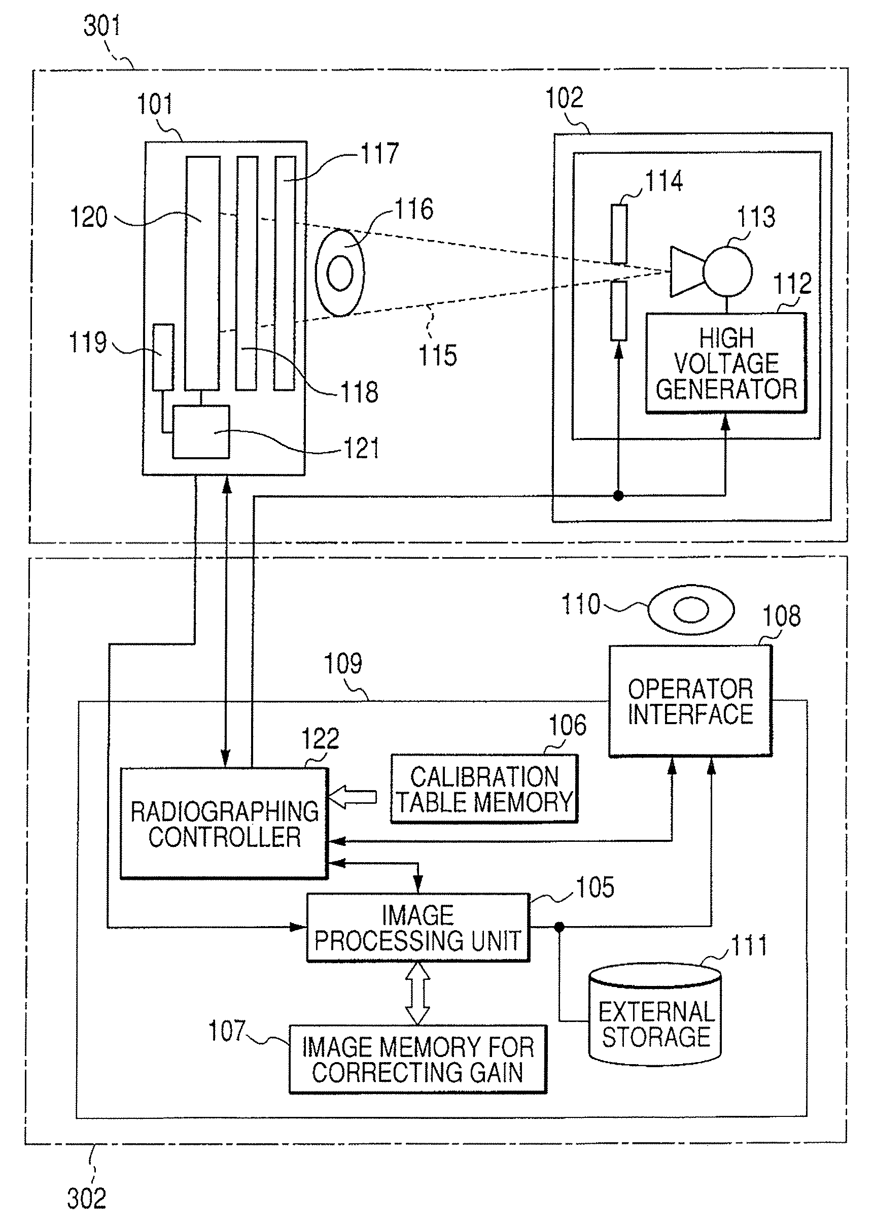
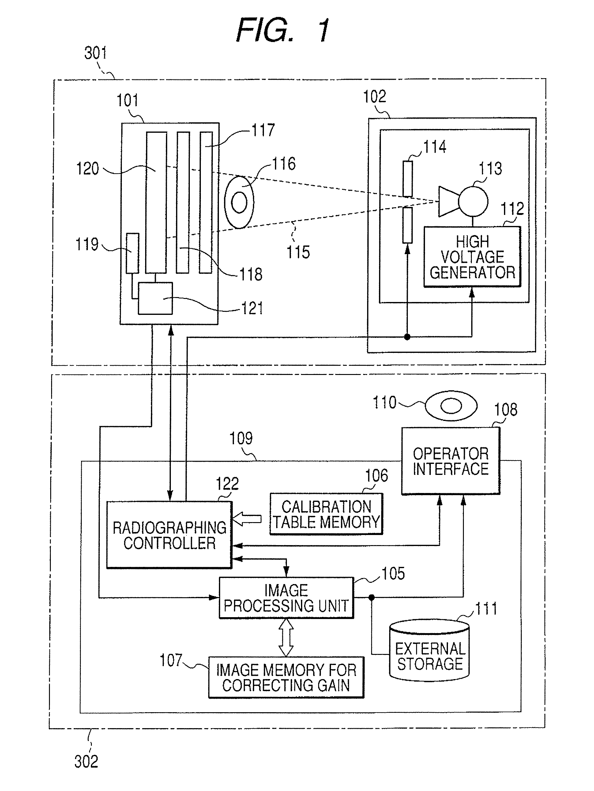
[0045]FIG. 1 is a schematic configuration view of an x-ray imaging system according to a first embodiment. As shown in FIG. 1, the radiation imaging system of the present embodiment is configured by being divided into an x-ray room 301 and an x-ray control room 302. In the x-ray room 301 are placed an x-ray imaging apparatus 101 and an x-ray generator apparatus 102. Further, a control apparatus 109 for controlling the x-ray imaging apparatus 101 and the x-ray generator apparatus 102 is placed in the x-ray control room 302, and an engineer 110 is configured to control the x-ray imaging apparatus 101 and the x-ray generator apparatus 102 from the x-ray control room 302.

[0046]The engineer 110 performs a control for the x-ray imaging apparatus 101 and the x-ray generator apparatus 102 through an operator interface 108. This operator interface 108 comprises a touch panel on a display, mouse, keyboard, joystick, foot switch, and the like. The engineer 110 can set irradiation conditions of...

second embodiment

[0131]Next, a second embodiment of the present invention will be described.

[0132]The configuration of a radiation imaging system according to the second embodiment is the same as the radiation imaging system according to the first embodiment shown in FIGS. 1 and 2. Further, the processing in the radiographing operation of the radiation imaging system according to the second embodiment is the same as the processing in the radiographing operation of the radiation imaging system according to the first embodiment shown in FIG. 8. In the radiation imaging system according to the second embodiment, since the difference with the radiation imaging system according to the first embodiment is only about an acquisition processing of an image for gain correction, the description thereof only will be made in the following.

[0133]FIG. 9 is a flowchart showing the acquisition processing of the image for gain correction of the x-ray imaging system according to the second embodiment. That is, FIG. 9 ...

third embodiment

[0148]Next, a third embodiment of the present invention will be described.

[0149]In a radiation imaging system according to the third embodiment, the difference with the radiation imaging system of the first embodiment is only about information on a calibration table stored in a calibration table memory 106, and the description thereof only will be made in the following.

[0150]FIG. 10 is a view showing one example of the calibration table used for the x-ray imaging system according to the third embodiment.

[0151]The calibration table in the third embodiment shown in FIG. 10, as compared to that of the first embodiment shown in FIG. 3, is read as the driving conditions of the x-ray imaging apparatus 101, and is added with a cut off frequency (fc) of a low pass filter in the Amp of a readout circuit unit 121b.

[0152]Further, in the present embodiment, as the driving conditions in the x-ray imaging apparatus 101, other than those shown in FIG. 10, the mode forming a calibration table furt...


PUM


Abstract

When a gain correction is performed for the radiographed object image, the acquisition of the object image having a high grade quality and no artifact is realized. For that purpose, an image storing unit is provided for storing an image for correction radiographed based on conditions set with the table in a state in which no object exists to each operation modes of the plurality of operation modes; and an image processing unit is provided for performing a gain correction processing of the radiographed object image and performs the gain correction processing of the radiographed object image obtained based on the conditions set in the table of the operation mode selected by the selecting unit in a state in which the object exists using a corresponding image for correction extracted from the image storage unit based on the operation mode selected by the selecting unit.

Description

BACKGROUND OF THE INVENTION[0001]1. Field of the Invention[0002]The present invention relates to a radiation imaging system for radiographing a radiation image of an object and a driving method thereof.[0003]2. Description of the Related Art[0004]In general, a demand for digitalization of an x-ray image in the hospital has been recently increasing. In reality, a radiation imaging apparatus such as, for example, FPD (Flat Panel Detector) has began to be used, in which an x-ray dosage is converted into electric signals by using a solid state imaging device in which x-ray detection elements (conversion elements) are disposed in a two-dimensional array pattern instead of a film.[0005]In this X-ray imaging apparatus, since an X-ray image can be replaced by digital information, the image information can be transferred far away and instantaneously and this provides the advantage of being able to receive a sophisticated diagnosis comparable to a university hospital in the heart of the city,...

Claims


Application Information

Patent Timeline
Patent Type & Authority Patents(United States)
IPC IPC(8): G01D18/00H05G1/58
CPCG01N23/04
Inventor TAKENAKA, KATSUROENDO, TADAOKAMESHIMA, TOSHIOYAGI, TOMOYUKIYOKOYAMA, KEIGO
Owner CANON KK
Why Eureka
Try Eureka