Radiation imaging system and apparatus and method for detecting defective pixel

a technology of diffraction grating and pixel, which is applied in the direction of material analysis using wave/particle radiation, instruments, applications, etc., can solve the problems of defective pixels, high production error, and inability to obtain sufficient contrast in the x-ray absorption image of living soft tissue or soft materials, etc., to achieve high accuracy

Inactive Publication Date: 2013-11-26
FUJIFILM CORP
View PDF12 Cites 50 Cited by
  • Summary
  • Abstract
  • Description
  • Claims
  • Application Information

AI Technical Summary

Benefits of technology

[0030]According to the defective pixel detection apparatus and the defective pixel detection method of present invention, the defective pixel is detected using the characteristic value of the intensity modulated signal from each pixel based on the fringe images obtained by the radiation image detector when the radiation is emitted from the radiation source. Thereby, the defective pixel caused only by the grating is detected with accuracy. More specifically, the defective pixel is detected based on the average value and the amplitude value of the intensity modulated signal. Thereby, the defective pixel caused by the grating deformation is detected with high accuracy.

Problems solved by technology

This causes a problem that a sufficient contrast cannot be obtained in the X-ray absorption image of living soft tissue or soft materials.
Inevitably, defective pixels occur.
In the above-described X-ray imaging system, the first and second diffraction gratings are required to be produced with high precision and a small production error.
Even a slight deformation in one of the first and second diffraction gratings causes a pixel in a position corresponding to the deformation to fail to detect a normal phase shift value.
As a result, the detection accuracy of the phase shift value is degraded, making it difficult to detect defective pixels caused by the grating deformation based on the absorption image.

Method used


Image

  • Radiation imaging system and apparatus and method for detecting defective pixel
  • Radiation imaging system and apparatus and method for detecting defective pixel
  • Radiation imaging system and apparatus and method for detecting defective pixel

Examples


first embodiment

[0046](First Embodiment)

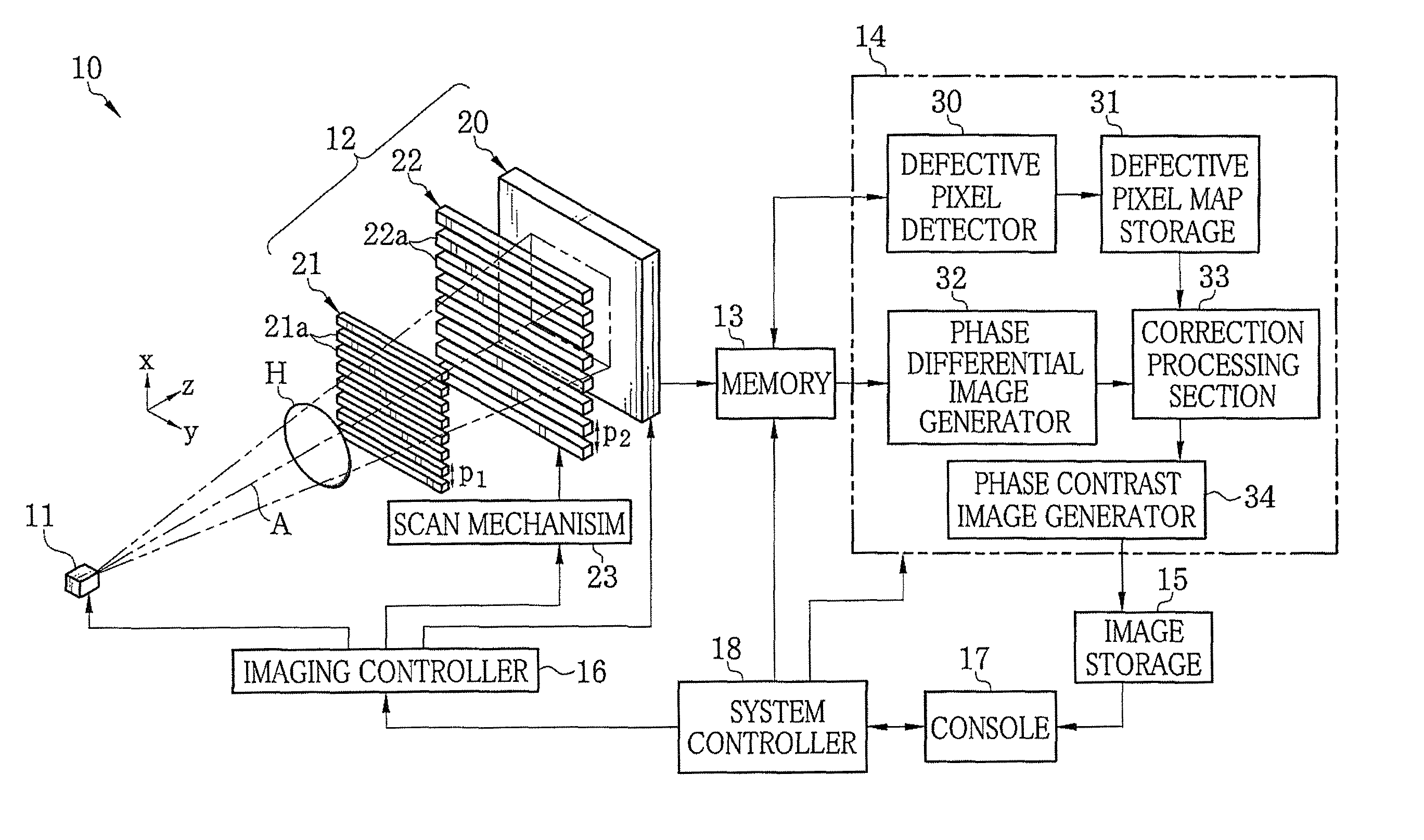
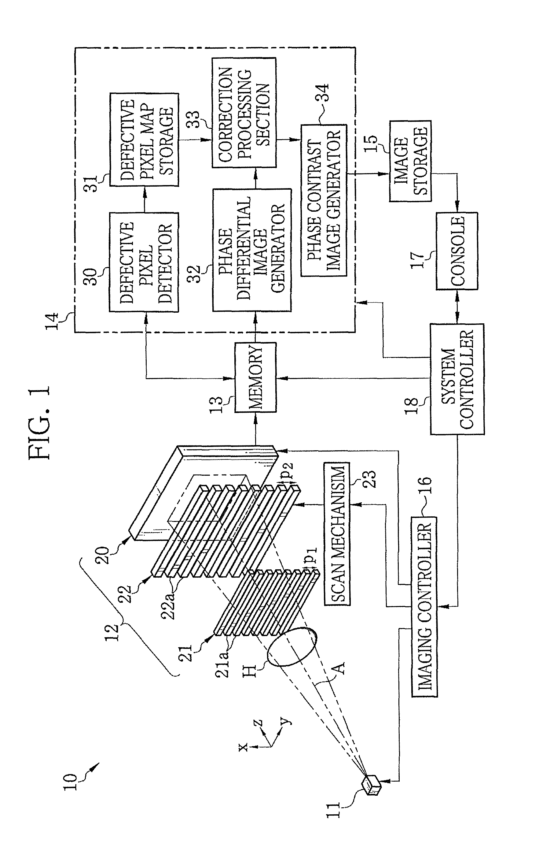
[0047]In FIG. 1, an X-ray imaging system 10 according to a first embodiment of the present invention is composed of an X-ray source 11, an imaging unit 12, a memory 13, an image processor 14, an image storage 15, an imaging controller 16, a console 17, and a system controller 18. The X-ray source 11 applies X-ray to an object H. The imaging unit 12 is opposed to the X-ray source 11 and detects the X-ray, emitted from the X-ray source 11 and passed through the object H, to generate image data. The memory 13 stores the image data read from the imaging unit 12. The image processor 14 processes multiple frames of image data stored in the memory 13 to generate a phase contrast image. The image storage 15 stores the phase contrast image generated by the image processor 14. The imaging controller 16 controls the X-ray source 11 and the imaging unit 12. The console 17 is composed of an operating section, a monitor, and the like. The system controller 18 controls the ...

second embodiment

[0123](Second Embodiment)

[0124]Next, a second embodiment of the present invention is described. The second embodiment is a variant of the detection process of the defective pixel performed by the defective pixel detector 30. In this embodiment, the correction processing section 33 performs the detection process following a flowchart shown in FIG. 12.

[0125]First, as with the first embodiment, when the calibration is instructed (“YES” in S20), the FPD 20 obtains the image data (the dark image) in a state that the X-ray irradiation from the X-ray source 11 or X-ray exposure is prohibited. The obtained dark image is stored in the memory 13 (S21). The defective pixel detector 30 reads the dark image stored in the memory 13. The defective pixel detector 30 judges a pixel having the pixel data (pixel noise value) larger than an allowable value as the defective pixel (S22).

[0126]Next, the fringe-scanning imaging is performed in a state that the X-ray having predetermined intensity is emitte...

third embodiment

[0133](Third Embodiment)

[0134]In the above embodiments, the second absorption grating 22 is provided independently of the FPD 20. With the use of an X-ray detector disclosed in U.S. Pat. No. 7,746,981 corresponding to Japanese Patent Laid-Open Publication No. 2009-133823, the second absorption grating 22 can be eliminated. The X-ray image detector is a direct conversion type X-ray image detector provided with a conversion layer and charge collection electrodes. The conversion layer converts the X-ray into electric charge. The charge collection electrodes collect the converted electric charge. The charge collection electrode in each pixel is composed of linear electrode groups arranged to have mutually different phases. Each linear electrode group is composed of linear electrodes arranged at a predetermined period and electrically connected to each other. The charge collection electrode constitutes the intensity modulator.

[0135]In FIG. 14, the X-ray image detector (FPD) of this embod...


PUM


Abstract

An X-ray imaging system includes an X-ray source, first and second absorption gratings, and an FPD. The first absorption grating passes X-ray emitted from the X-ray source to form a G1 image. The second absorption grating modulates intensity of the G1 image at each of relative positions to form two or more fringe images. The relative positions differ in phase with respect to a period pattern of the G1 image. The FPD detects two or more frames of image data of the fringe images. A defective pixel detector reads two or more frames of image data stored in a memory and obtains a characteristic value of an intensity modulated signal on a pixel-by-pixel basis based on the read image data. The defective pixel detector detects a defective pixel based on the characteristic value obtained.

Description

FIELD OF THE INVENTION[0001]The present invention relates to a radiation imaging system for capturing an image of an object using radiation such as X-ray and more particularly to a radiation imaging system for performing radiation phase imaging using a grating arranged between a radiation source and a radiation image detector, and an apparatus and method for detecting a defective pixel of the radiation image detector.BACKGROUND OF THE INVENTION[0002]X-ray attenuates while it passes through a substance. The attenuation depends on an atomic number of an element constituting the substance and density and thickness of the substance. A probe for examining the inside of an object using X-ray exploits this X-ray attenuation property. X-ray imaging is commonly used in medical diagnoses and non-destructive inspections.[0003]A common X-ray imaging system captures a radiograph or X-ray transmission image of an object arranged between an X-ray source for applying X-ray and an X-ray image detect...

Claims


Application Information

Patent Timeline
Patent Type & Authority Patents(United States)
IPC IPC(8): G01D18/00
CPCA61B6/00A61B6/484A61B6/585G01T1/2985G01T7/005A61B6/4291A61B6/4021
Inventor TADA, TAKUJI
Owner FUJIFILM CORP
Why Eureka
Try Eureka