Micro-speaker box

a micro-speaker box and box body technology, applied in the field of speakers, can solve the problems of increased sharp peak/dip in the reproduction frequency, difficult disposal of such materials, and none of the above materials are cheap

Inactive Publication Date: 2013-11-21
AAC MICROTECH CHANGZHOU +1
View PDF3 Cites 40 Cited by
  • Summary
  • Abstract
  • Description
  • Claims
  • Application Information

AI Technical Summary

Problems solved by technology

Hence, there is a difficulty that a sharp peak/dip is increased in the reproduction frequency.
However, none of the above materials are cheap because many steps are required in their manufactured, and disposal of such materials is not easy.
Also, there is a case in which the attenuation effect of a sound wave does not meet expectations.
Some little sound waves input into the cabinet may leak outside of the cabin...

Method used


Image

  • Micro-speaker box
  • Micro-speaker box

Examples


Embodiment Construction

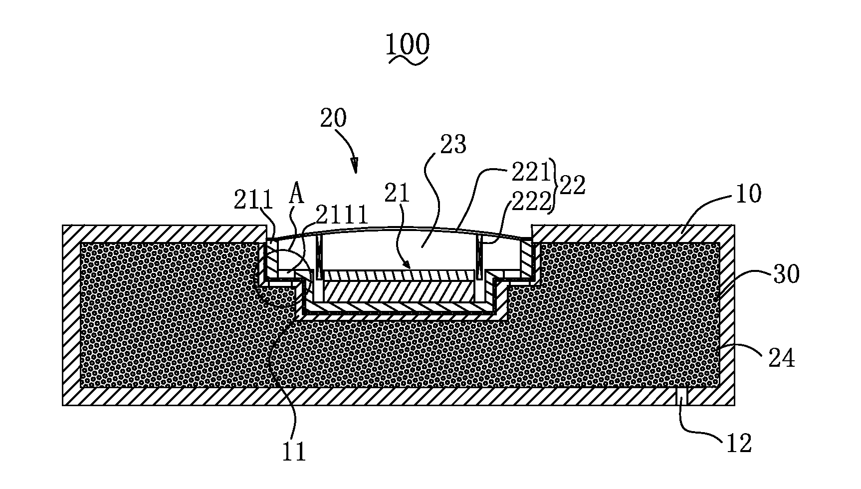
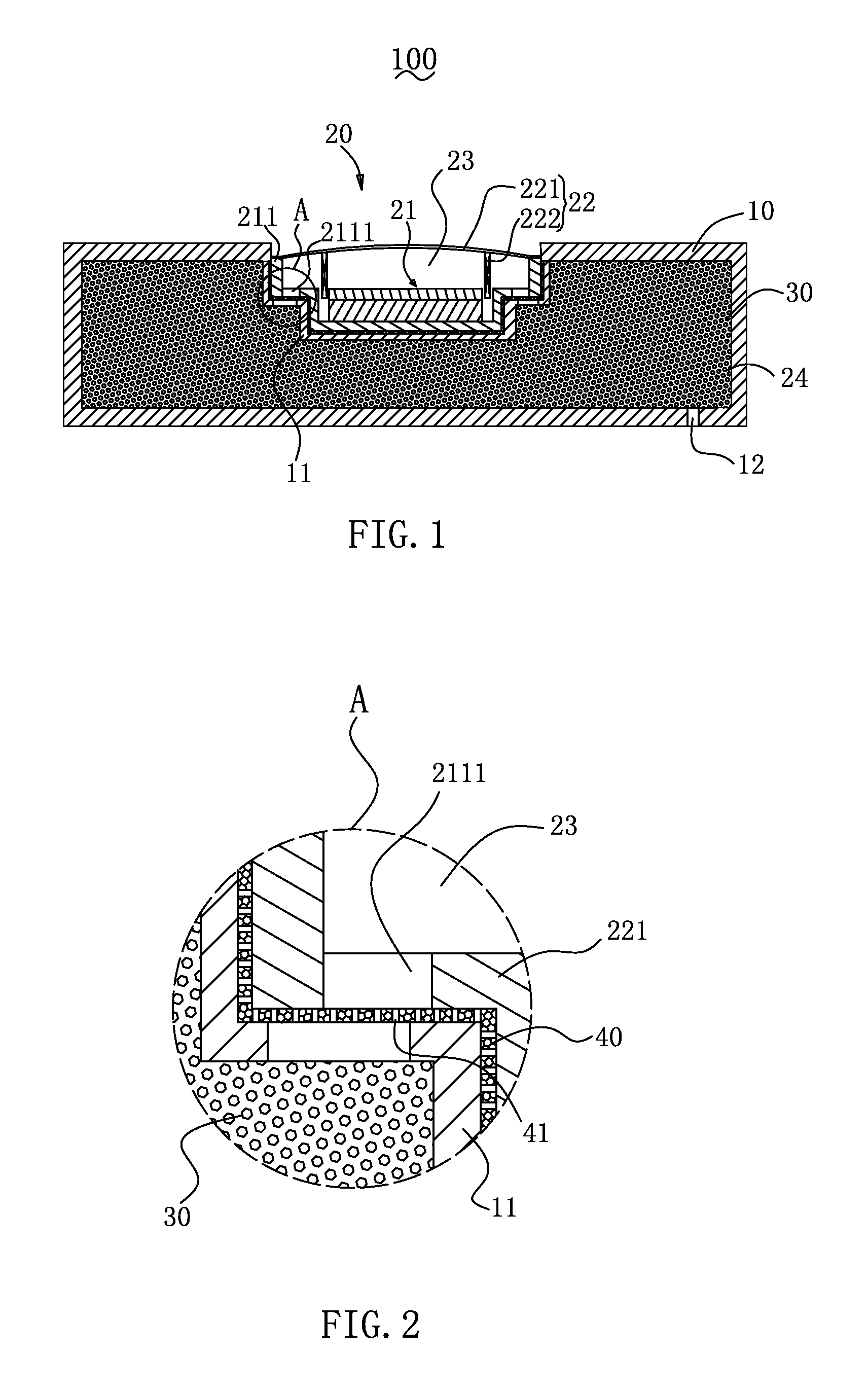
[0013]A micro-speaker box in accordance with an exemplary embodiment of the present invention is used for converting audio electrical signals to audible sounds. The micro-speaker box includes a cabinet, and a speaker unit attached to the cabinet. The speaker unit has a magnetic circuit, at least a vibrating unit corresponding to the magnetic circuit, at least a pair of welding pads for electrically connecting with the vibrating unit for conducting electrical signals to the vibrating units.

[0014]Referring to FIGS. 1 and 2, a micro-speaker box 100, in accordance with an exemplary embodiment of the present disclosure, includes a cabinet 10 with a cavity room, a speaker unit 20 attached to the cabinet 10, and an adsorbent 30 located in the inside of the cabinet 10.

[0015]The speaker unit 20 defines a magnetic circuit unit 21, and a vibrating unit 22 corresponding to the magnetic circuit unit 21. In the present embodiment, the magnetic circuit unit 21 has a yoke 211 mounted on the cabinet...


PUM


Abstract

A micro-speaker box includes a cabinet with a cavity room, a speaker unit, an amount of adsorbents located in the inside of the cabinet, and a porous layer arranged in the cavity room and dividing the cavity room of the cabinet into twp parts, one part for accommodating the speaker unit, the other part filled with the adsorbents. The porous layer defines an acoustical airflow resistance no more than 150 MKS Rayls, and includes billions of stomas. The stomas in the porous layer have diameters in the range of 1 um to 500 um.

Description

FIELD OF THE INVENTION[0001]The present disclosure relates to the art of speakers and, particularly to a micro-speaker box provided with adsorbent material for converting electrical signals including audio information to audible sounds.DESCRIPTION OF RELATED ART[0002]As described in US Pat. Pub. No. 2008-0149418 A1, A speaker system is provided with a speaker unit and a cabinet (enclosure). The speaker unit can be classified as a full range, a tweeter, a midrange, and a woofer depending on a sound reproduction band. As for the cabinet to which the speaker unit is attached, a rear open type and a closed type are known, and the type is selected depending on its manner of use.[0003]The foregoing speaker cabinet basically uses a baffle plate (front surface plate) having a unit mounting port to which the speaker cabinet is attached and has top, bottom, left and right plate-shaped portions, which are bent behind the mounting plate. Thus, a standing wave is generated inside the cabinet whe...

Claims


Application Information

Patent Timeline
IPC IPC(8): H04R1/28
CPCH04R1/288
Inventor SHEN, TAO
Owner AAC MICROTECH CHANGZHOU
Why Eureka
Try Eureka