
Improvements in Turbines

Active Publication Date: 2013-11-21
WAVE POWER RENEWABLES
View PDF5 Cites 4 Cited by
  • Summary
  • Abstract
  • Description
  • Claims
  • Application Information

AI Technical Summary

Benefits of technology

The patent text explains that using rotor blades and guide vanes with smooth surfaces and rounded edges improves the efficiency of energy conversion modules and turbines. This is because a greater amount of working fluid is captured and used to rotate the rotors, resulting in increased operation of the turbine.

Problems solved by technology

The problem with many such systems proposed to date is that a significant capital outlay is required to set up a new system.
The extent of this capital outlay can often act as a deterrent to investors, as the return on investment is limited to some extent by the relationship between the capital outlay and the efficiency of the system.
The turbines currently employed in such systems operate at a relative low efficiency and the energy extraction system as a whole is limited by the efficiency of these turbines.

Method used


Image

  • Improvements in Turbines
  • Improvements in Turbines
  • Improvements in Turbines

Examples


Embodiment Construction

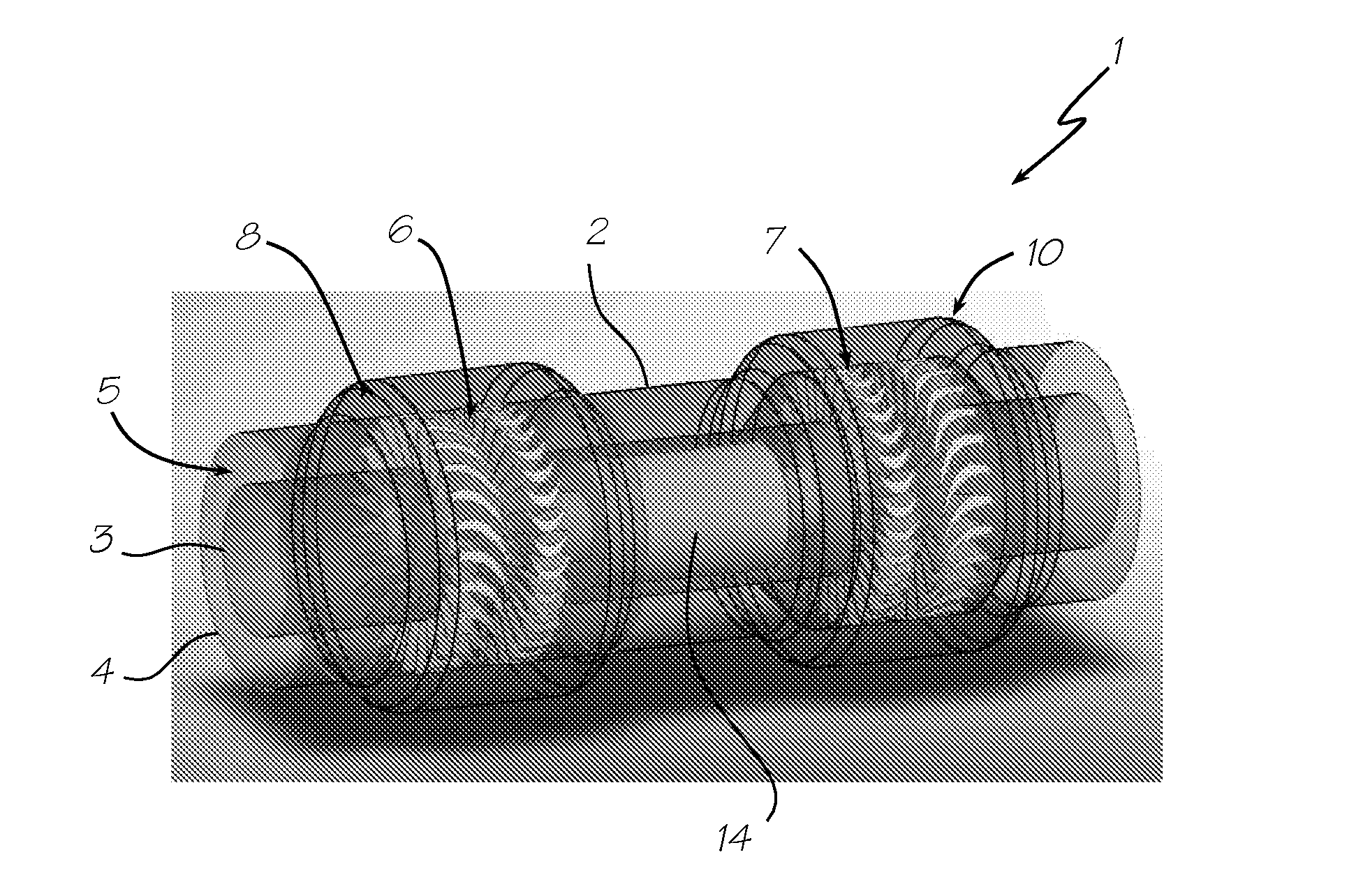
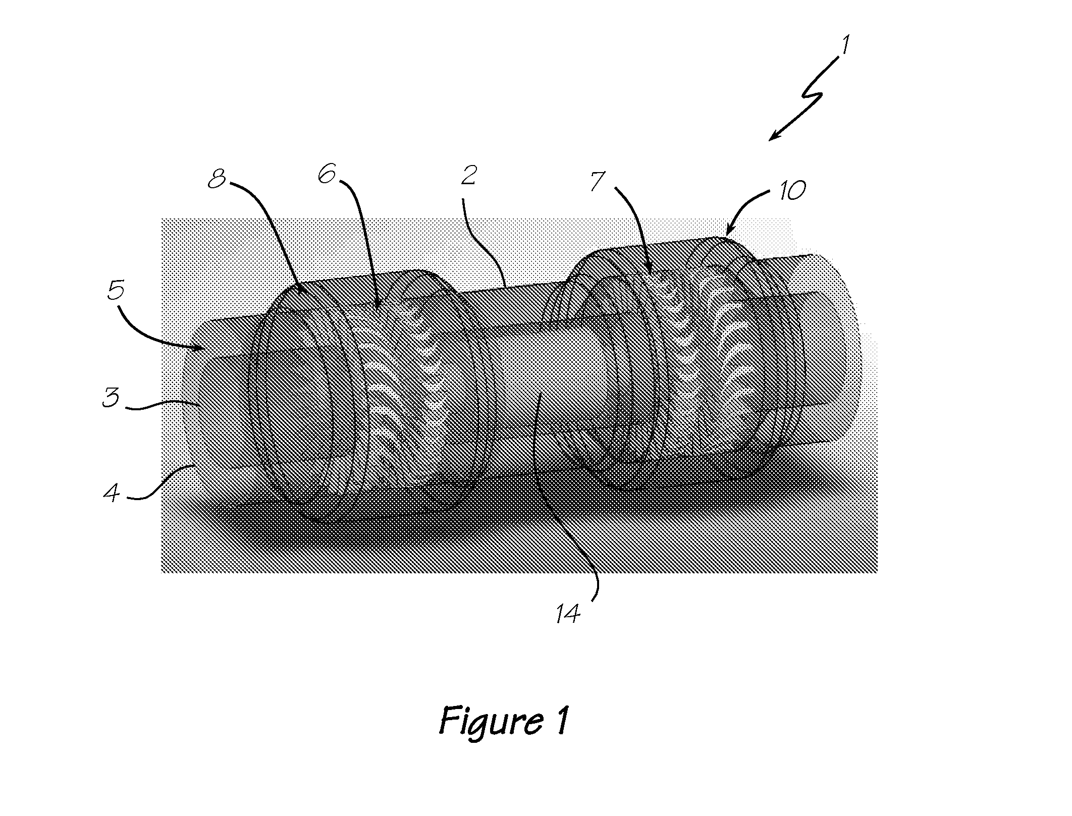
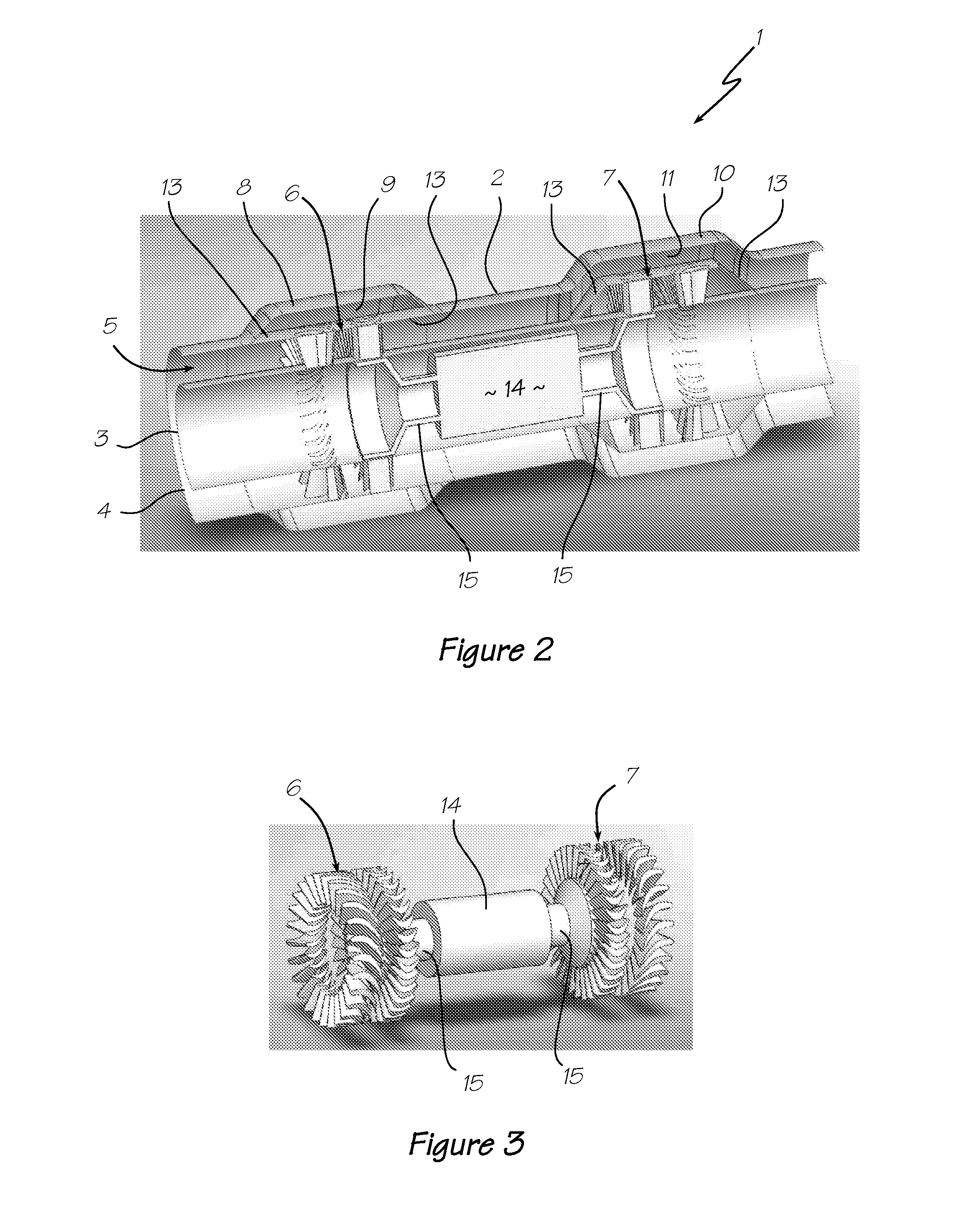
[0093]Referring to the drawings, the invention provides a turbine 1 for extracting energy from an oscillating working fluid in the form of an oscillating airflow. The turbine 1 has been developed specifically for use in an ocean wave energy extraction system (not shown) of the type having an oscillating water column. In such systems, the oscillating water column or OWC is configured to produce the oscillating airflow in response to the rise and fall of passing ocean waves.

[0094]The turbine 1 has a longitudinal, generally cylindrical housing 2 having an inner frame 3 and an outer frame 4. The inner and outer frames (3, 4) are arranged concentrically about the longitudinal axis of the housing 2 such that the void or space therebetween forms a central flow passage 5 for the working fluid. The concentric arrangement of the inner and outer frames (3, 4) is such that the cross-section of the central flow passage 5 is in the form of an annulus.

[0095]An energy conversion unit having a first...


PUM


Abstract

This invention relates to a turbine for extracting energy from an oscillating working fluid. The turbine includes a housing defining a flow passage for the working fluid. An energy conversion unit is disposed in the housing. Flow control means is selectively movable to occlude a predetermined portion of the flow passage such that the working fluid is directed to act on a certain section of the energy conversion unit.

Description

FIELD OF THE INVENTION[0001]The present invention relates generally to energy conversion devices and in particular to turbines.[0002]The invention has been developed primarily for use in an ocean wave energy extraction system employing an oscillating water column and will be described hereinafter with reference to this application. However, it will be appreciated that the invention is not limited to this particular filed of use.BACKGROUND OF THE INVENTION[0003]With an ever increasing concern of the impact traditional energy systems have had or are having on the environment, new methods and systems are currently being developed for reducing the impact such systems have on the environment.[0004]A number of these systems rely on turbines to rotate an electric generator in order to produce electricity. The problem with many such systems proposed to date is that a significant capital outlay is required to set up a new system. The extent of this capital outlay can often act as a deterrent...

Claims


Application Information

Patent Timeline
IPC IPC(8): F03B15/06
CPCF03B15/06F03B15/02F05B2210/404F03B11/004F03B13/142F03B13/24F05B2240/12Y02E10/30Y02E10/20F03B13/22
Inventor HUNTER, SCOTTNANEHKARAN, ALI MOHAMMAD BAGHAEI
Owner WAVE POWER RENEWABLES
Learn More