Methods and apparatus for constructing a power supply capable drawing power from fluorescent lamps

a technology of power supply and fluorescent lamp, which is applied in the direction of light source, electric lighting source, light source, etc., to achieve the effect of efficient and effective power supply, improving efficiency and operation of low-frequency transformer

Inactive Publication Date: 2005-08-25
THOMAS J MAYER
View PDF10 Cites 1 Cited by
  • Summary
  • Abstract
  • Description
  • Claims
  • Application Information

AI Technical Summary

Benefits of technology

[0030] When receiving a low frequency power source a capacitor placed across the primary windings of the low-frequency transformer can act as a power factor correction device and will compensate for the resistance of the high-frequency transformer and improve the efficiency and operation of low-frequency transformer. When receiving a high frequency power source, the same capacitor across the primary windings of the low-frequency transformer will act as a bypass device and shunt the majority of the power to the high-frequency transformer. This will allow a single power supply to efficiently and effectively supply power from either a high frequency or a low frequency power source.

Problems solved by technology

When a low frequency power source is applied to the input of the series of transformers the high-frequency transformer will be designed of a material, such as powdered iron, so it will be ineffective at low frequencies and the core of the transformer will not pass significant amounts of energy to its secondary winding.

Method used


Image

  • Methods and apparatus for constructing a power supply capable drawing power from fluorescent lamps
  • Methods and apparatus for constructing a power supply capable drawing power from fluorescent lamps
  • Methods and apparatus for constructing a power supply capable drawing power from fluorescent lamps

Examples


Embodiment Construction

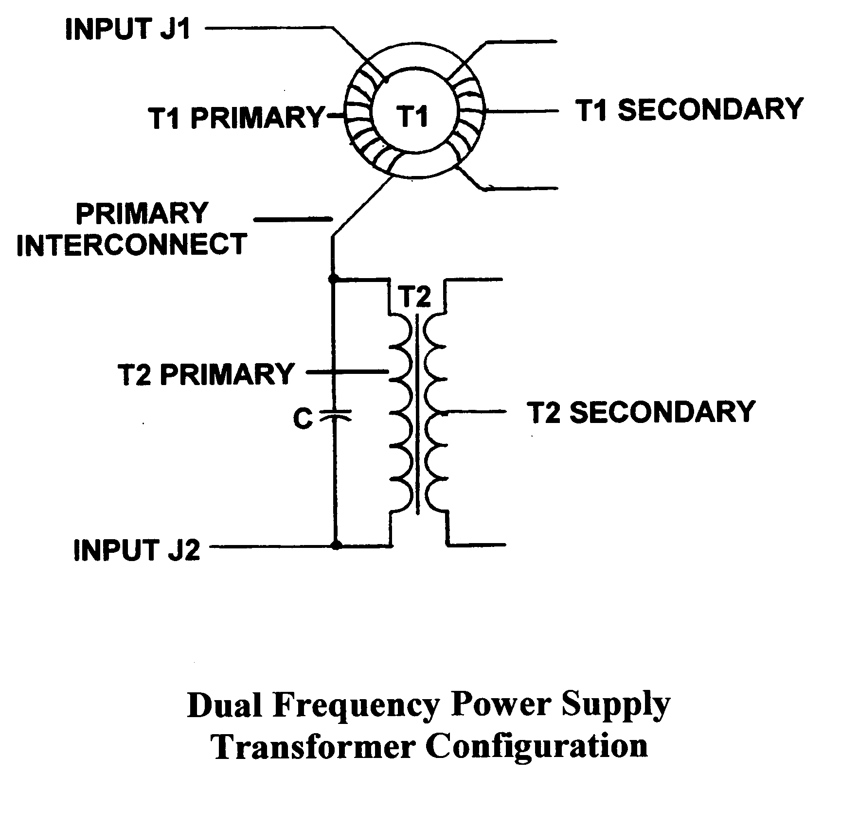
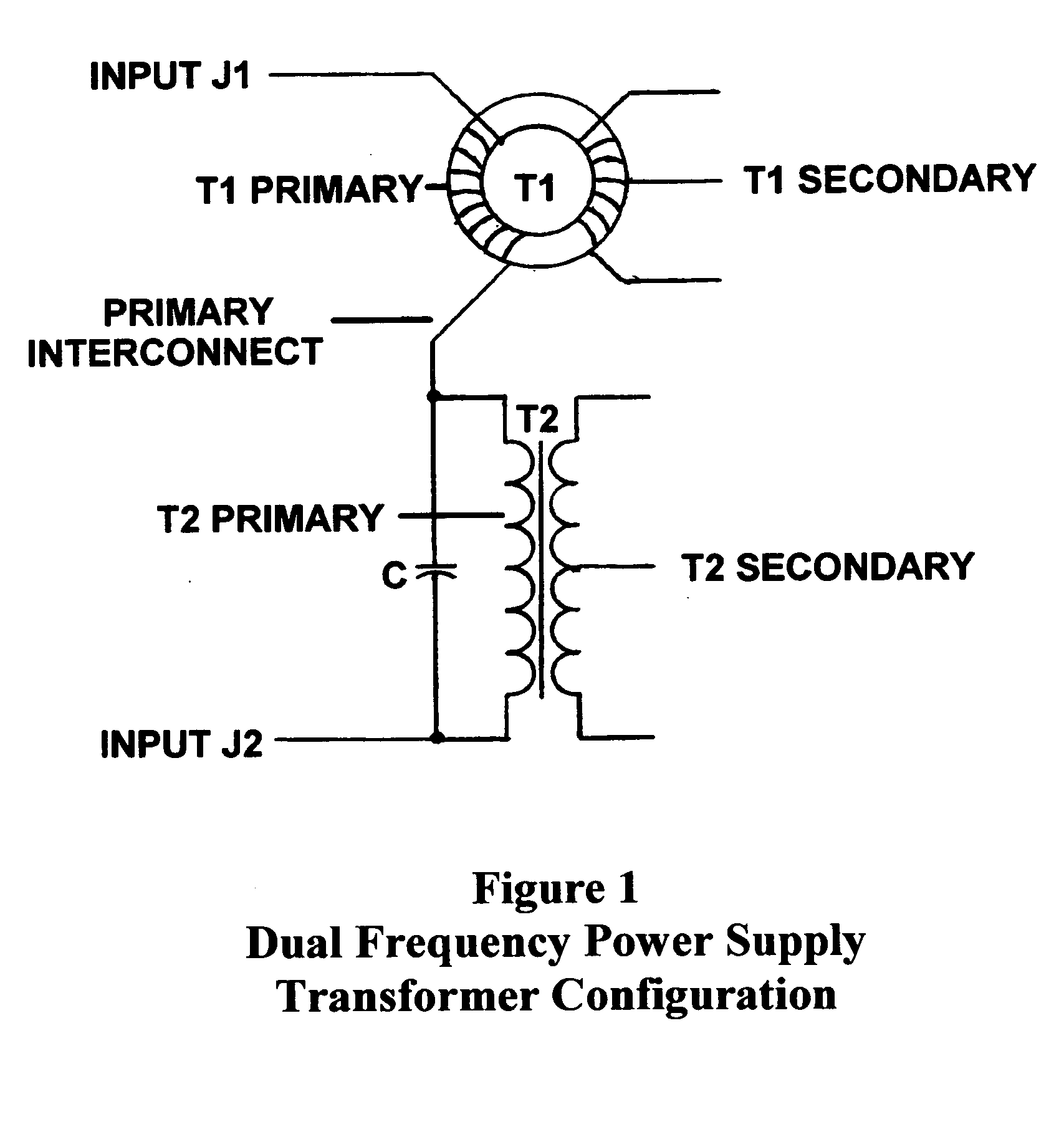
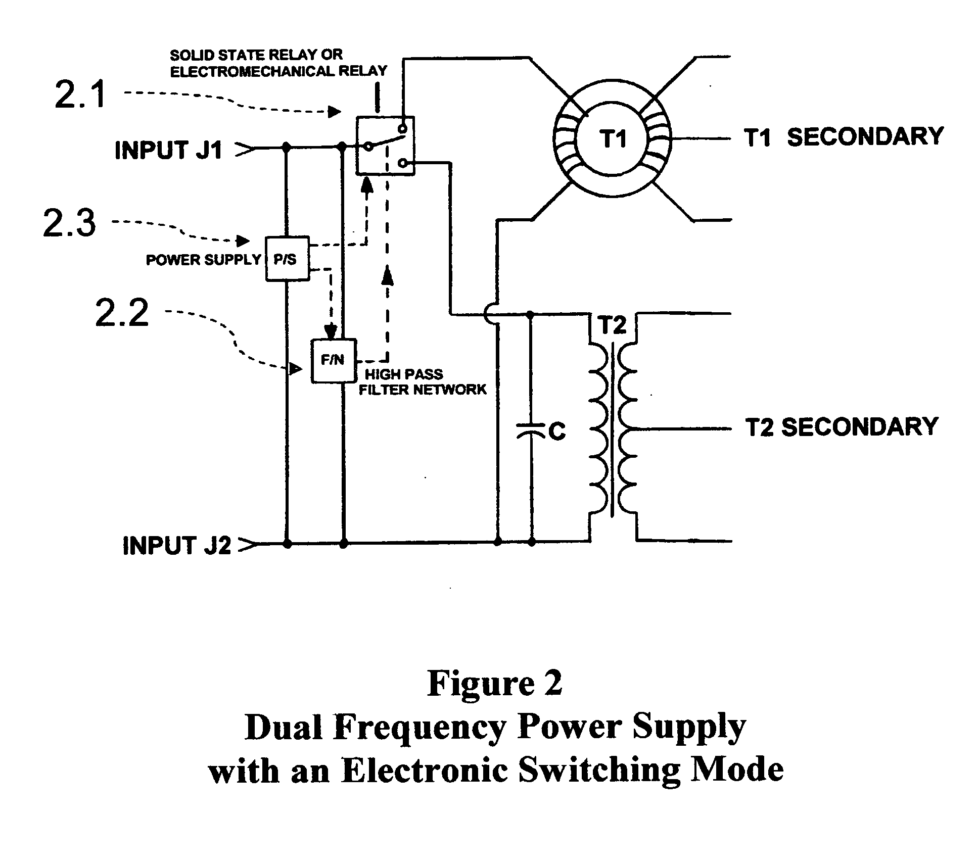
[0045] Referring to FIG. 1 In the operation of a Dual Frequency transformer(s) described herein, the basic function of each of the transformer(s) utilized is assumed to be of common knowledge to any person practiced in the art, and it shall be the unique combination of these conventional transformer(s) that will be described in detail below.

[0046] Transformer One (T1), as indicated in FIG. 1, shall represent a High Frequency transformer having a core material that is powdered iron or other such material that would operate efficiently in a High Frequency application. The type of material chosen would reflect the specific requirements for both power and frequency.

[0047] Transformer Two (T2), as indicated in FIG. 1, shall represent a Low Frequency transformer having a core material this is silicon steel or other such material that would operate efficiently in a Low Frequency application. The type of material chosen would reflect the specific requirements for both power and frequency....


PUM


Abstract

Methods and Apparatus are provided for a power supply capable of being operated directly from fluorescent lighting fixture and capable to functioning properly when supplied by conventional 60 cycles per second (cps) “Core and Coil’ fluorescent lamp power supply (ballasts) as well as ‘Electronic’ or ‘Solid State’ ballasts functioning at frequencies from 20,000 cps to as much as 40,000 cps, without adversely affecting normal lighting fixture operation.

Description

RELATED APPLICATIONS CLAIMING PRIORITY [0001] The present application claims the benefit of the following two provisional patent applications, which are each incorporated herein by reference: (i) U.S. Provisional Patent Application Ser. No. 60 / 546,468 entitled “METHODS AND APPARATUS FOR CONSTRUCTING A POWER SUPPLY CAPABLE OF DUAL FREQUENCY INPUT”, filed Feb. 19, 2004; (ii) U.S. Provisional Patent Application Ser. No. 60 / 547,574 entitled—METHODS AND APPARATUS FOR CONSTRUCTING A DUAL FREQUENCY REGULATED POWER SUPPLY filed Feb. 24, 2003.TECHNICAL FIELD [0002] The present invention relates generally to a power supply that derives its voltages from the lamp to fixture interface of a fluorescent light. This power supply is primarily intended to be used in a wired or wireless communications network and more particularly to the use of radio communications networks in a dwelling, commercial building, campus environment, tunnels and / or neighborhoods. BACKGROUND OF THE INVENTION [0003] In rece...

Claims


Application Information

Patent Timeline
Patent Type & Authority Applications(United States)
IPC IPC(8): H05B41/298
CPCH05B41/2983
Inventor MAYER, THOMAS J.ROACH, PETER O. JR.
Owner THOMAS J MAYER
Why Eureka
Try Eureka