
Apparatus, system, and method for efficiently increasing exhaust flow temperature for an internal combustion engine

a technology of exhaust gas and internal combustion engine, which is applied in the direction of machines/engines, instruments, output power, etc., can solve the problems of limited theoretical effect of altering the timing of introduced fuel for increasing exhaust flow temperature, affecting the operation and efficiency of aftertreatment components, and affecting the temperature generation within the aftertreatment device. achieve the effect of efficiently and efficiently increasing the exhaust flow temperature, improving the operation and efficiency of aftertreatment components, and efficient and efficient exhaust flow

Active Publication Date: 2012-01-10
CUMMINS INTPROP INC
View PDF52 Cites 4 Cited by
  • Summary
  • Abstract
  • Description
  • Claims
  • Application Information

AI Technical Summary

Benefits of technology

"The present invention provides an apparatus, system, and method for increasing the exhaust flow temperature of an internal combustion engine. The apparatus, system, and method automatically and efficiently increase the exhaust flow temperature within a given range to improve the operation and efficiency of aftertreatment components of the engine. The method involves interpreting an exhaust flow temperature requirement indicator, surveying a plurality of engine operating conditions, and determining a crankshaft angle target for an exhaust valve open mode. The apparatus, system, and method can be implemented as a computer program product. The technical effect of the invention is to improve the performance and efficiency of aftertreatment components of combustion engines."

Problems solved by technology

One challenge of dosing systems is a significant time lag between the beginning of dosing and the increase of temperature within the aftertreatment system.
A major challenge experienced with in-cylinder dosing is that, to prevent fouling of components ion the recycle stream, and unknown quantities of fuel recycling to the intake air and disrupting the designed engine torque and air-fuel ratios, the exhaust gas recirculation (EGR) system is usually closed during periods of dosing.
However, altering the timing of introduced fuel has limited theoretical effectiveness for increasing exhaust flow temperatures.
Further, the pressure pulses produced by this method have only limited affect on temperature generation within the aftertreatment device.
Current exhaust temperature increase methods especially lack capability at low engine exhaust flow and power output.
Current methods of increasing exhaust flow temperatures to regenerate aftertreatment components have limited effectiveness, or significantly increase emissions during operation.
Other challenges of current methods include slow response to an exhaust temperature change request, insufficient temperature generation in the exhaust flow, and insufficiently precise temperature ranges produced for effective and efficient operation of aftertreatment components.

Method used


Image

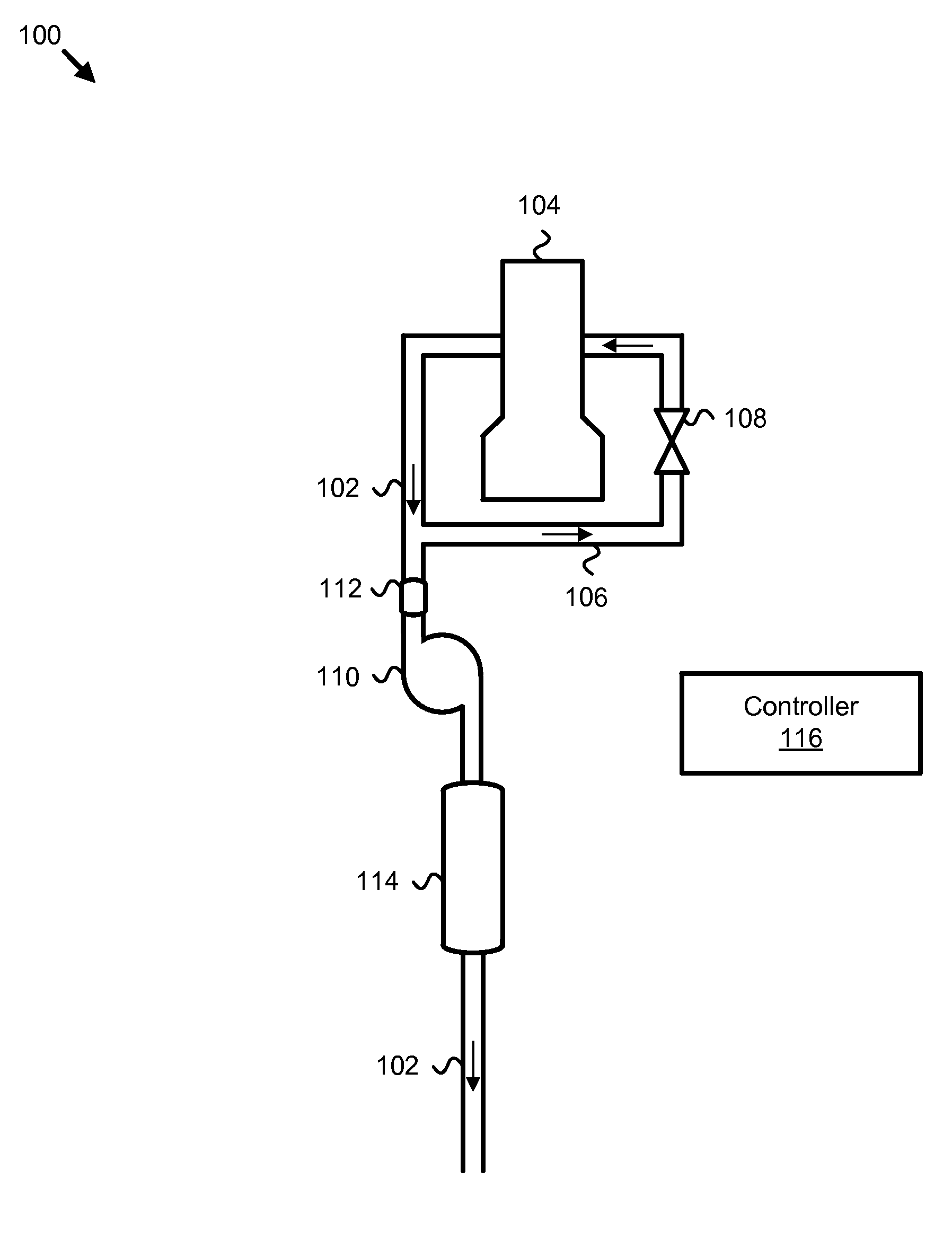
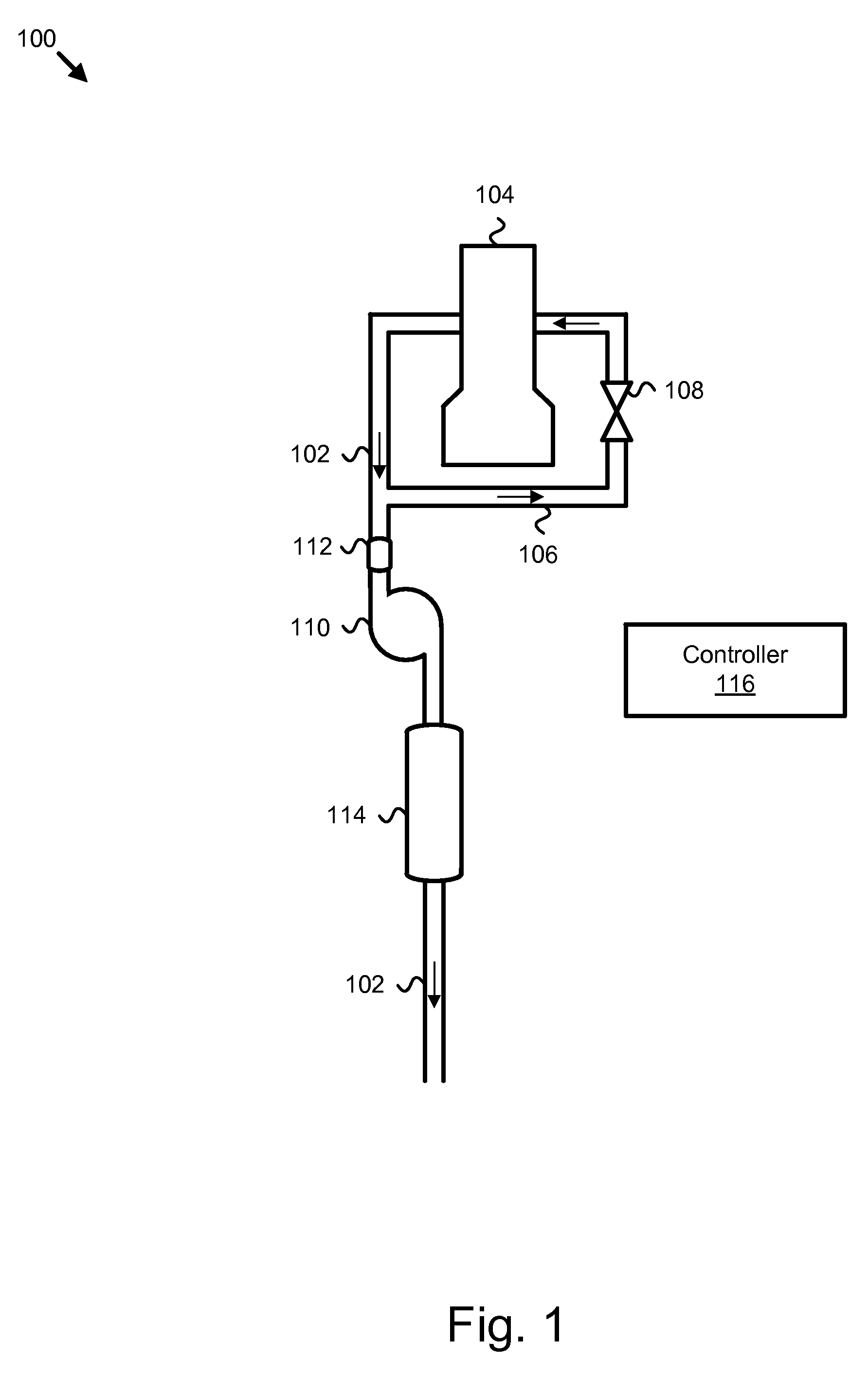
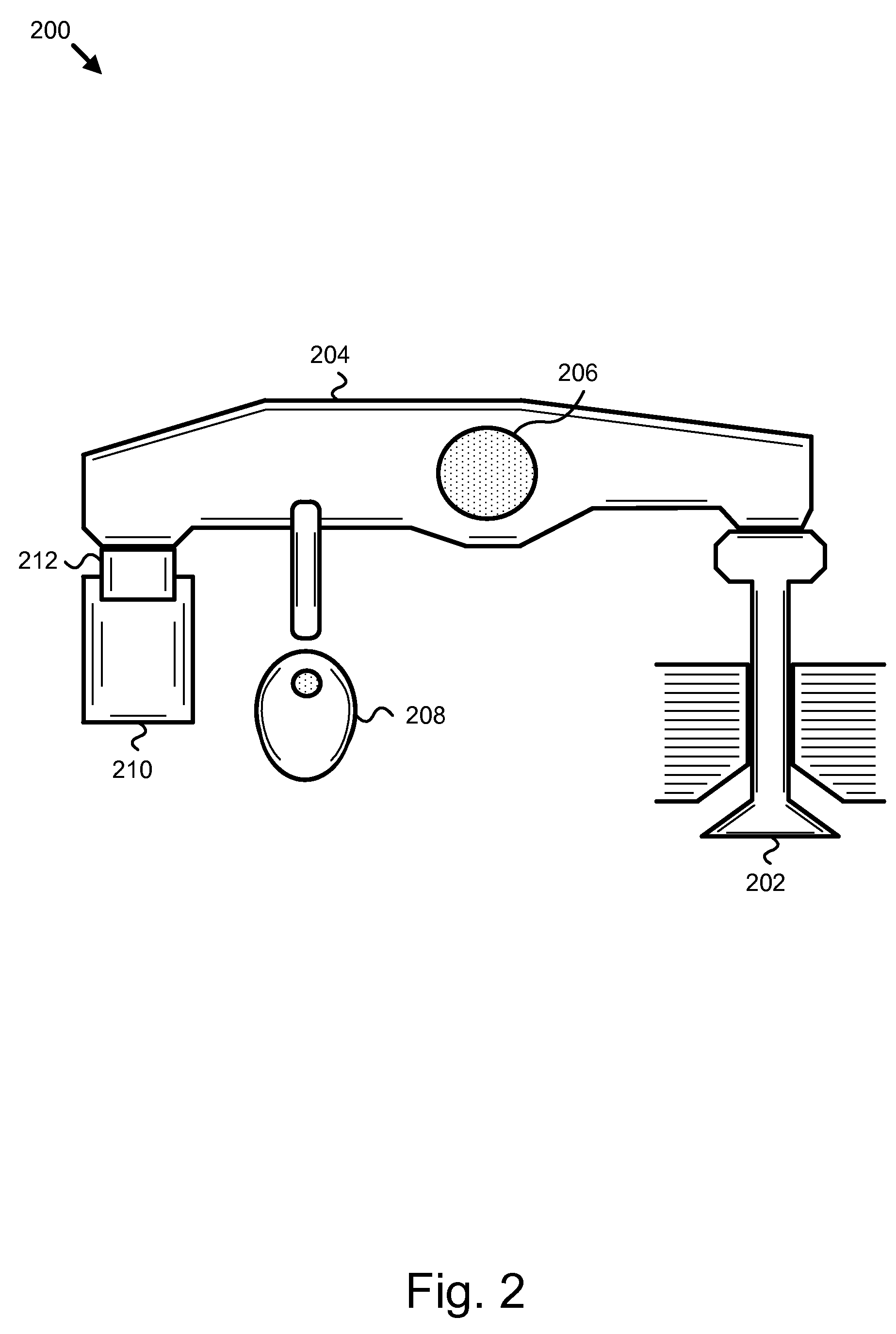
  • Apparatus, system, and method for efficiently increasing exhaust flow temperature for an internal combustion engine
  • Apparatus, system, and method for efficiently increasing exhaust flow temperature for an internal combustion engine
  • Apparatus, system, and method for efficiently increasing exhaust flow temperature for an internal combustion engine

Examples


Embodiment Construction

[0043]Many of the functional units described in this specification have been labeled as modules, in order to more particularly emphasize their implementation independence. For example, a module may be implemented as a hardware circuit comprising custom VLSI circuits or gate arrays, off-the-shelf semiconductors such as logic chips, transistors, or other discrete components. A module may also be implemented in programmable hardware devices such as field programmable gate arrays, programmable array logic, programmable logic devices or the like.

[0044]Modules may also be implemented in software for execution by various types of processors. An identified module of executable code may, for instance, comprise one or more physical or logical blocks of computer instructions which may, for instance, be organized as an object, procedure, or function. Nevertheless, the executables of an identified module need not be physically located together, but may comprise disparate instructions stored in d...


PUM


Abstract

An apparatus, system, and method are disclosed for efficiently increasing exhaust flow temperature for an internal combustion engine. The method includes excepting a user input to disable an exhaust valve opening mechanism. The method further includes monitoring exhaust gas mass flows and temperatures, interpreting required exhaust temperatures for aftertreatment devices, and surveying a plurality of operating conditions for a combustion engine. The method includes determining a crankshaft angle for dynamically engaging an exhaust valve open mode based on the exhaust temperature, the required exhaust temperature, and the engine operating conditions. Dynamically engaging the exhaust valve open mode includes selecting a specific crankshaft angle for each combustion cycle of the engine.

Description

BACKGROUND OF THE INVENTION[0001]1. Field of the Invention[0002]This invention relates to engine exhaust gas systems for internal combustion engines, and more particularly relates to increasing exhaust flow temperatures for aftertreatment devices.[0003]2. Description of the Related Art[0004]Environmental concerns motivate emissions requirements for internal combustion engines throughout much of the world. Governmental agencies, such as the Environmental Protection Agency (EPA) in the United States, carefully monitor the emission quality of engines and set acceptable emission standards, to which all engines must comply. Generally, emission requirements vary according to engine type and intended use. Emission requirements for compression-ignition (diesel) engines typically dictate the release of diesel particulate matter (DPM), nitrogen oxides (NOX), and unburned hydrocarbons (UHC).[0005]The need to comply with emissions requirements encourages the development of exhaust gas aftertrea...

Claims


Application Information

Patent Timeline
Patent Type & Authority Patents(United States)
IPC IPC(8): F01N3/00F01N3/10F01L1/34
CPCF02D13/0242F02D13/0273F01N3/10Y02T10/18Y02T10/22Y02T10/12
Inventor FARRELL, LISA A.FRAZIER, TIMOTHY R.MILLER, KYLE
Owner CUMMINS INTPROP INC
Learn More