

Medical apparatus
- Summary
- Abstract
- Description
- Claims
- Application Information
AI Technical Summary
Benefits of technology
Problems solved by technology
Method used
Image

Examples
first embodiment
A. First Embodiment
A-1. Apparatus Configuration
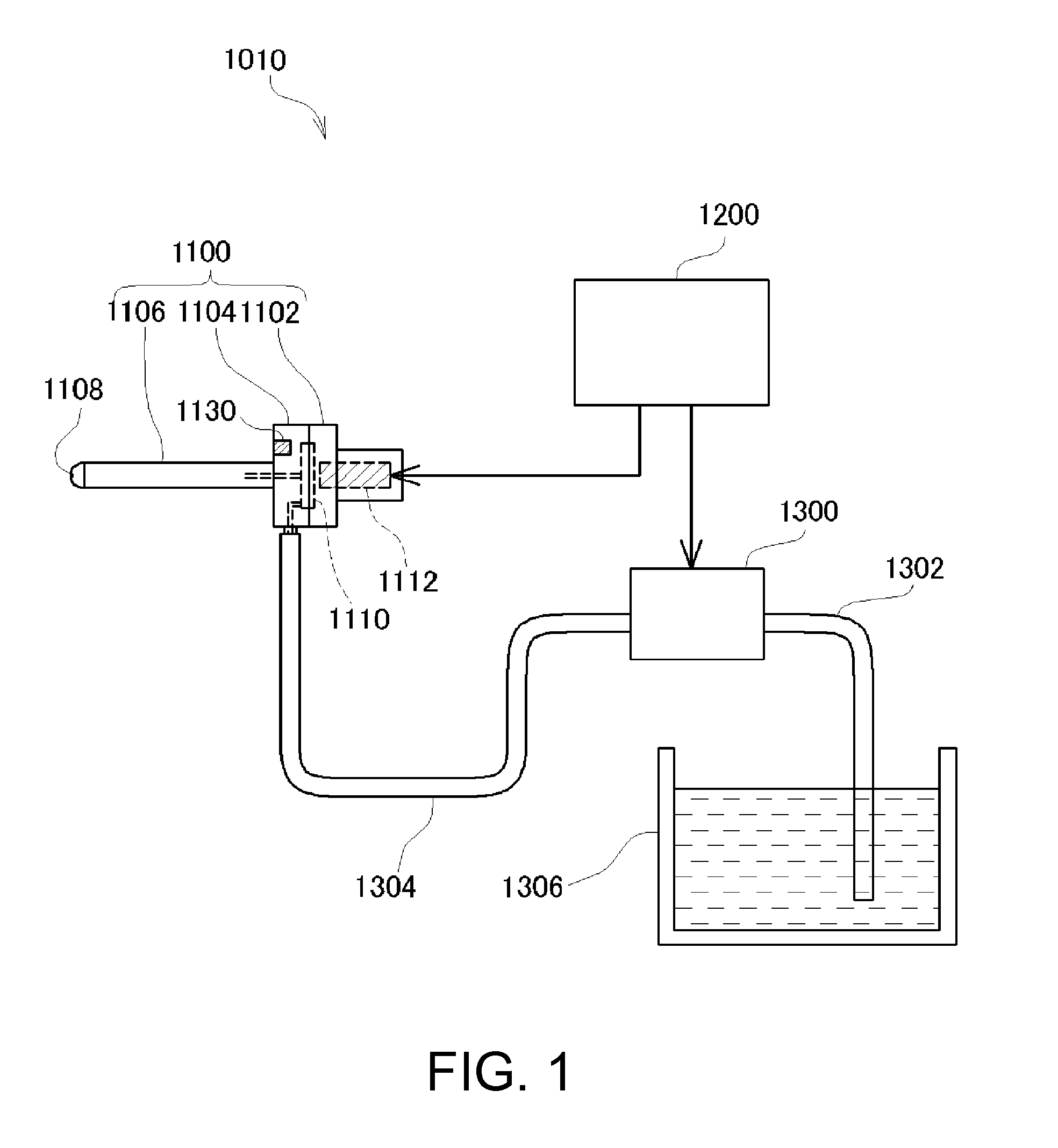
[0045]FIG. 1 is an explanatory diagram showing a rough configuration of a medical apparatus 1010 in a first embodiment. The medical apparatus 1010 shown in the figure is used for a surgical operation method for incising or excising a biological tissue by ejecting liquid such as water or saline to the biological tissue.
[0046]As shown in the figure, the medical apparatus 1010 in the first embodiment includes an applicator 1100 held by an operator by hand and operated to eject liquid, a liquid supply unit 1300 configured to supply the liquid to the applicator 1100, a liquid container 1306 configured to store the liquid to be ejected, and a control unit 1200 configured to control the operation of the applicator 1100 and the liquid supply unit 1300.
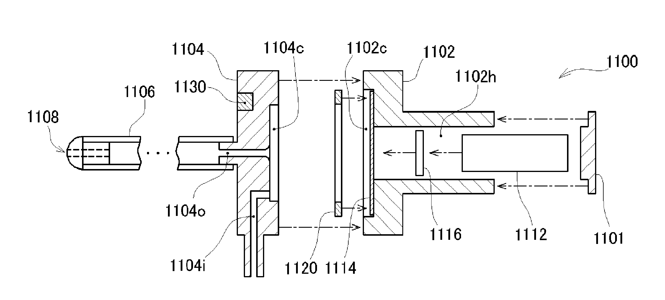
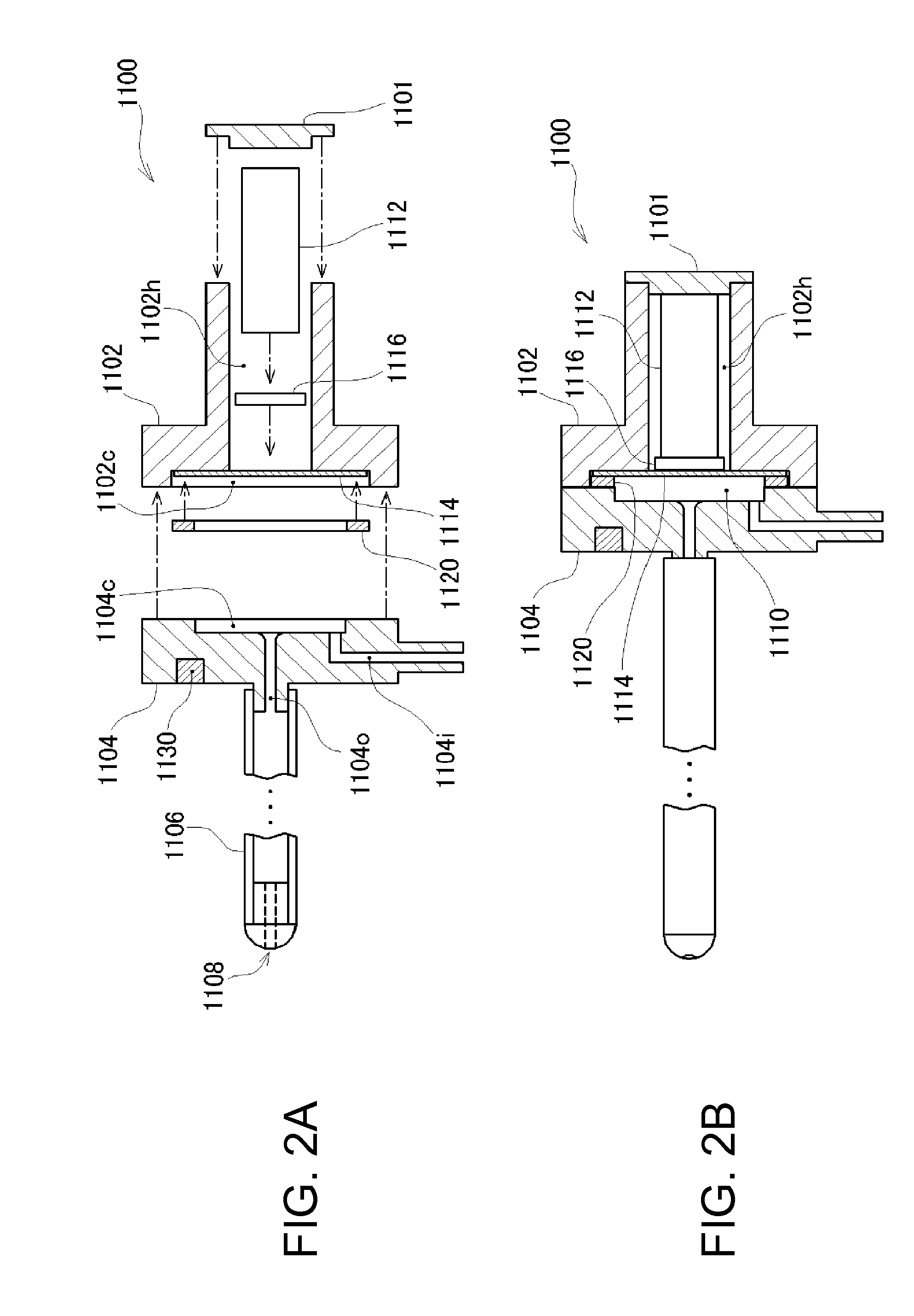
[0047]The applicator 1100 includes a first case 1102, a second case 1104 attached to the first case 1102, a liquid ejection pipe 1106 provided to project from the second case 1104 to the opposite ...
second embodiment
C. Second Embodiment
C-1. Apparatus Configuration
[0073]A second embodiment of the invention is explained. FIG. 12 is an explanatory diagram showing a rough configuration of a medical apparatus 2010 according to the second embodiment. The medical apparatus 2010 shown in the figure is used for a surgical operation method for incising or excising a biological tissue by ejecting liquid such as water or saline to the biological tissue.
[0074]As shown in the figure, the medical apparatus 2010 in the second embodiment includes an applicator 2100 held by an operator by hand and operated to eject liquid, a liquid supply unit 2300 configured to supply the liquid to the applicator 2100, a liquid container 2306 configured to store the liquid to be ejected, and a control unit 2200 configured to control the operation of the applicator 2100 and the liquid supply unit 2300.
[0075]The applicator 2100 includes a first case 2102, a second case 2104 attached to the first case 2102, a liquid ejection pipe ...
third embodiment
E. Third Embodiment
E-1. Apparatus Configuration
[0106]A third embodiment of the invention is explained. FIG. 21 is an explanatory diagram showing a rough configuration of a medical apparatus 3010 according to this embodiment. The medical apparatus 3010 shown in the figure is used for a surgical operation method for incising or excising a biological tissue by ejecting liquid such as water or saline to the biological tissue.
[0107]As shown in the figure, the medical apparatus 3010 in this embodiment includes an applicator 3100 held by an operator by hand and operated to eject liquid, a liquid supply unit 3300 configured to supply the liquid to the applicator 3100, a liquid container 3306 configured to store the liquid to be ejected, a camera 3150 configured to photograph a state in which the applicator 3100 is operated, and a control unit 3200 configured to control the operation of the applicator 3100 and the liquid supply unit 3300.
[0108]The applicator 3100 includes a first case 3102, ...
PUM
 Abstract
Description
Claims
Application Information