
Spinal Implants for Rotationally Adjusting Vertebrae

a technology of rotational adjustment and spinal implants, applied in the field of spinal surgery, can solve the problems of inconvenient operation, inconvenient use, etc., and achieve the effect of reducing the risk of scoliosis and improving the quality of li

Inactive Publication Date: 2013-11-21
NUVASIVE
View PDF7 Cites 53 Cited by
  • Summary
  • Abstract
  • Description
  • Claims
  • Application Information

AI Technical Summary

Benefits of technology

This patent describes a device for replacing a damaged spinal disc. The device has two arrays of ridges that can move relative to each other during application of a force. The ridges can be made of magnetic material, which helps to ensure a better match between the ridges and reduces the force required to displace the arrays. This design makes it easier to repair the spinal disc.

Problems solved by technology

Scoliosis can result in abnormal curvature in the coronal plane to cause lateral curvature, abnormal curvature in the coronal plane associated with incorrect lordosis and / or kyphosis, and abnormal axial alignment of the spine to cause incorrect rotation.
Traditional manual methods for estimating of the vertebral axial rotation in scoliosis based on X-ray images were relative imprecise.

Method used


Image

  • Spinal Implants for Rotationally Adjusting Vertebrae
  • Spinal Implants for Rotationally Adjusting Vertebrae
  • Spinal Implants for Rotationally Adjusting Vertebrae

Examples


Embodiment Construction

[0097]Illustrative embodiments of the invention are described below. In the interest of clarity, not all features of an actual implementation are described in this specification. It will of course be appreciated that in the development of any such actual embodiment, numerous implementation-specific decisions must be made to achieve the developers' specific goals, such as compliance with system-related and business-related constraints, which will vary from one implementation to another. Moreover, it will be appreciated that such a development effort might be complex and time-consuming, but would nevertheless be a routine undertaking for those of ordinary sill in the art having the benefit of this disclosure. The disc replacement system and related methods disclosed herein boasts a variety of inventive features and components that warrant patent protection, both individually and in combination.

[0098]In general, the spinal implants described in this document include a pair of rotatably...


PUM


Abstract

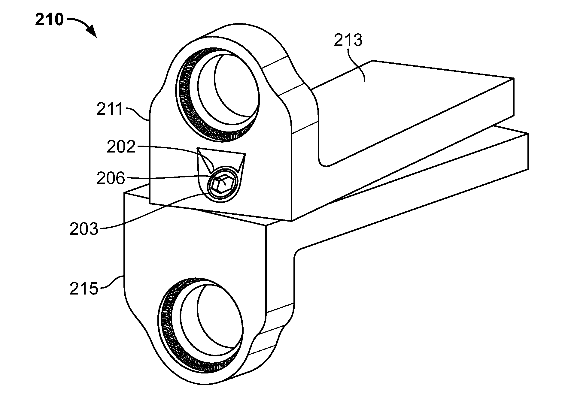
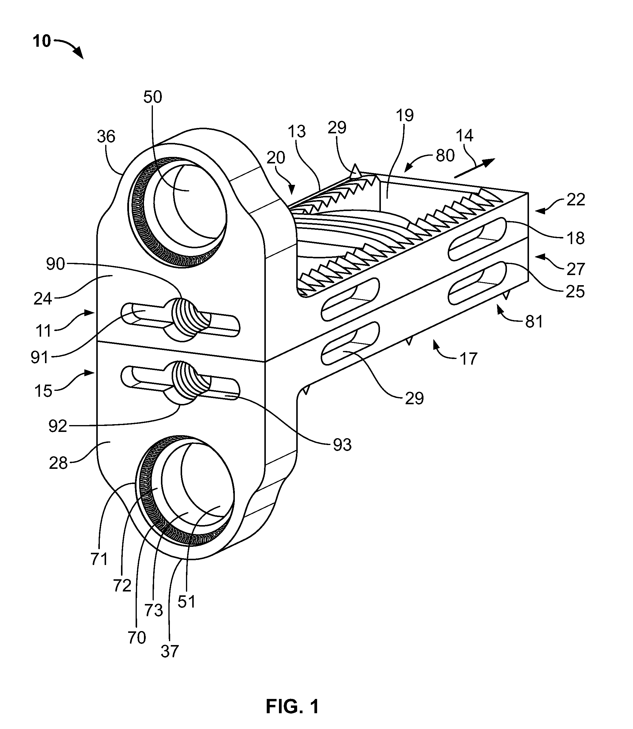
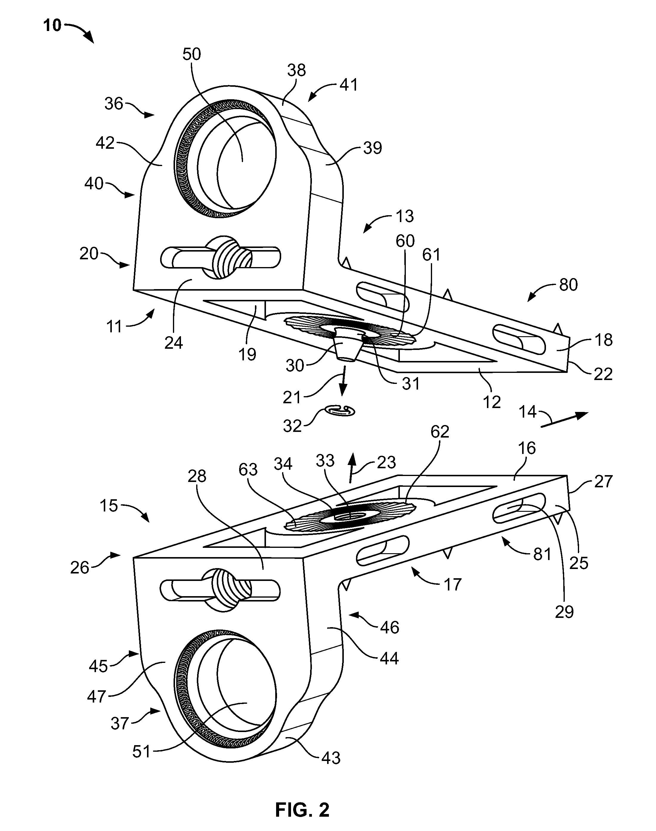
A spinal implant adapted to be positioned within a disc space between adjacent vertebrae includes a first intradiscal element, a second intradiscal element, and a coupling mechanism. The first and second intradiscal elements include respective first and second outer surfaces adapted to be positioned adjacent an endplate of respective first and second adjacent vertebrae. The first and second intradiscal elements further include respective first and second medial surfaces that are opposite the respective first and second outer surfaces, where the second medial surface is adapted to generally face the first medial surface upon assembly of the first intradiscal element with the second intradiscal element. The coupling mechanism is associated with the first and second medial surfaces and is adapted to provide relative rotational movement between the first and second intradiscal elements in a plane generally parallel with the first and second medial surfaces.

Description

CROSS-REFERENCE TO RELATED APPLICATIONS[0001]This application claims priority to U.S. Provisional Application Ser. No. 61 / 436,172, filed on Jan. 25, 2011, entitled SPINAL DEROTATION IMPLANT, the disclosure of which is incorporated herein by reference.TECHNICAL FIELD[0002]This document describes systems, devices and methods that relate generally to spinal surgery and, more particularly, to disc replacement systems and related methods for correction of spinal deformities, such as scoliosis, kyphosis, and lordosis.BACKGROUND[0003]Scoliosis is characterized by abnormal curvature of the spine. Scoliosis can result in abnormal curvature in the coronal plane to cause lateral curvature, abnormal curvature in the coronal plane associated with incorrect lordosis and / or kyphosis, and abnormal axial alignment of the spine to cause incorrect rotation. Scoliosis may therefore present as a tridimensional deformity of the spine.[0004]The spine is made up of vertebrae connected by discs. Scoliosis c...

Claims


Application Information

Patent Timeline
IPC IPC(8): A61F2/44
CPCA61F2/4425A61B17/86A61F2/447A61F2/4611A61F2002/2835A61F2002/30006A61F2002/30052A61F2002/30079A61F2002/30331A61F2002/30364A61F2002/30365A61F2002/30367A61F2002/30387A61F2002/3039A61F2002/30426A61F2002/30428A61F2002/30433A61F2002/30462A61F2002/30469A61F2002/305A61F2002/30505A61F2002/3052A61F2002/30522A61F2002/3054A61F2002/30578A61F2002/30616A61F2002/30785A61F2002/30823A61F2002/30825A61F2002/30841A61F2002/30894A61F2002/30904A61F2310/00011A61F2310/00017A61F2310/00023A61F2310/00179
Inventor PIMENTA, LUIZ
Owner NUVASIVE
Learn More