
Neuromuscular Model-Based Sensing And Control Paradigm For A Robotic Leg

a robotic leg and neural model technology, applied in the field of neural model-based sensing and control paradigm of a robotic leg, can solve the problems of only being able to reconfigure the joint angle, not providing sufficient stance phase power, and not being able to adapt biomimetically to changes in terrain slope and walking speed

Inactive Publication Date: 2013-11-21
MASSACHUSETTS INST OF TECH
View PDF6 Cites 224 Cited by
  • Summary
  • Abstract
  • Description
  • Claims
  • Application Information

AI Technical Summary

Benefits of technology

This patent describes a system for controlling a robotic limb that can adapt to changes in speed and terrain. The system uses a neuromuscular model to control the movement of the limb joints, which adjusts the parameters that determine the relation between muscle force, length, and velocity. This allows for a more intuitive response to changes in the environment and the wearer's intent, as conveyed by extrinsic signals. The technical effect is a more efficient and effective robotic arm that can adapt to its surroundings and the person wearing it.

Problems solved by technology

Generally, existing commercially available prostheses, such as active ankle prostheses, are only able to reconfigure joint angle in response to very limited external factors.
For example, available microprocessor-controlled ankle prostheses typically are only able to reconfigure ankle joint angle during a swing phase, requiring several strides to converge to a terrain-appropriate ankle position at first ground contact.
Further, such ankle prostheses generally do not provide sufficient stance phase power for normal gait, and therefore cannot adapt biomimetically to changes in terrain slope and walking speed.
Although somewhat effective at their intended steady-state gait speed and terrain, such controllers generally do not allow for adaptation to environmental disturbances such as speed transients and rapid intra-step terrain variations.

Method used


Image

  • Neuromuscular Model-Based Sensing And Control Paradigm For A Robotic Leg
  • Neuromuscular Model-Based Sensing And Control Paradigm For A Robotic Leg
  • Neuromuscular Model-Based Sensing And Control Paradigm For A Robotic Leg

Examples


example i

Human Walking Models

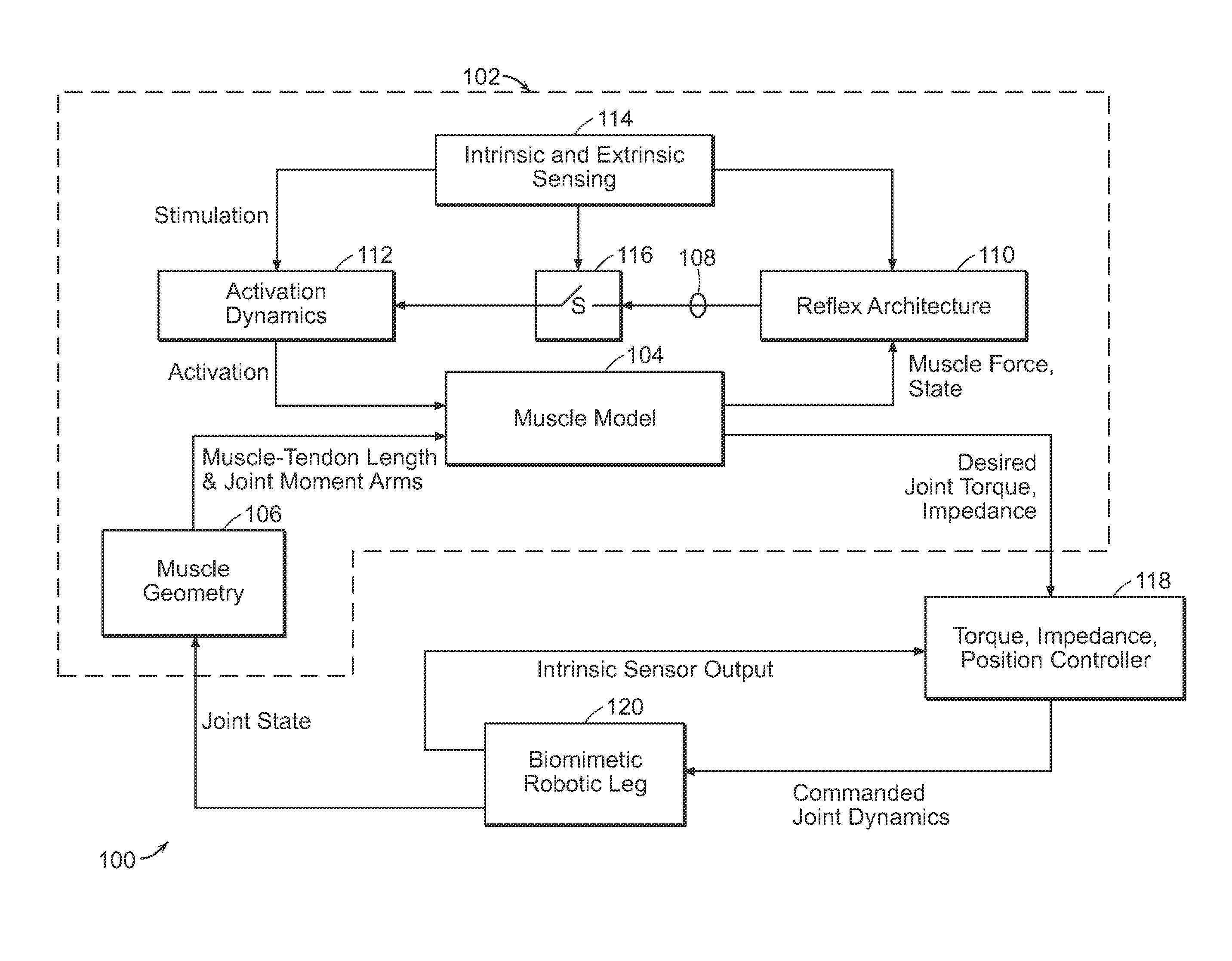
[0069]Two human walking models are described that may be applied in the control of prosthetic, orthotic and exoskeletal components. It is important to note that these are only two of many models that may be used for this purpose. These models do, however, lend themselves well to the task; since they include reflex feedback-based neural control schemes that fit neatly into the framework illustrated in FIG. 1.

a. Neuromuscular Model with Hill-Type Muscle Elements

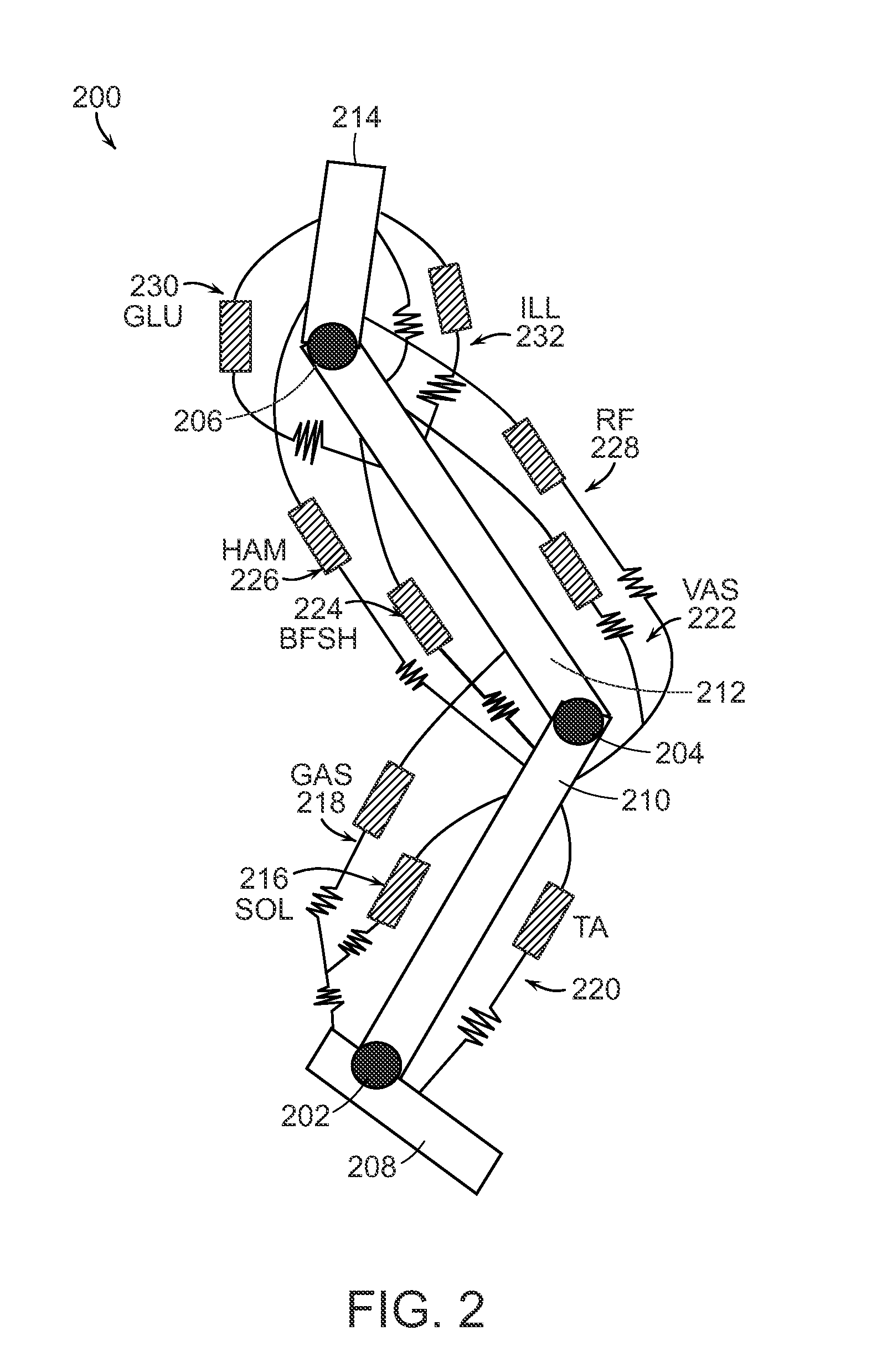
[0070]In this section, a lumped-parameter neuromuscular model for walking is described that includes Hill-type representations of all the major muscle groups of the leg (FIG. 2). FIG. 2 illustrates neuromuscular model 200 comprising ankle 202, knee 204 and hip 206 joints connected by rigid bodies representing the human trunk 214 and two, three-segment legs, each leg including a foot 208, a shank 210, and a thigh 212. As shown in FIG. 2, nine muscle-tendon units were modeled: soleus (SOL) 216, gastrocnemius (...

example ii

Application of a Neuromuscular Model to Prosthetic Control

[0174]A neuromuscular model of the function of the ankle joint during level ground, self-selected speed walking was developed by Krishnaswamy et al. (Krishnaswamy, P., Brown, E. N., Herr, H. M. (2011) Human Leg Model Predicts Ankle Muscle-Tendon Morphology, State, Roles and Energetics in Walking. PLoS Comput Biol 7(3): e1001107. doi:10.1371 / journal.pcbi.1001107). This model encompassed the inverse step described in Example I (a), supra, but only for the ankle joint. In the following example, we describe the application of this model to control of a powered ankle-foot prosthesis. Emergent speed adaptive behavior was observed using this linear, reflex-based controller. No intrinsic or extrinsic sensing was employed in this example to modulate or tune the reflexive parameters with walking gait speed. Here reflexive parameters include, but are not limited to, thresholds, gains, and exponents on the feedback signals of muscle forc...

example iii

Extrinsic Neural Sensing for the Modulation of Reflexive Parameters

[0259]As mentioned earlier, it may be beneficial to incorporate neural input into model-based control schemes of artificial joints. While there are many ways to obtain such input, one particularly attractive method is the collection of surface EMG data from the residual limb muscles. In this section, we describe the use of EMG signals to directly modulate the parameters of a reflexive control scheme. In this example, the EMG signal is measured using surface EMG signals from electrodes sewn into a socket liner used by a transtibial amputee. These EMG signals were filtered and used to modify feedback gains, producing adaptive behavior with walking speed and stair ascent / descent. We expect that additional advances in neural sensing technology will allow even more meaningful data to be input to robotic prostheses, orthoses and exoskeletons, enabling further adaptive behavior.

EMG Control of Prosthetic Ankle Plantar Flexio...


PUM


Abstract

A neuromuscular model-based controller for a robotic limb having at least one joint includes a neuromuscular model having a muscle model, muscle geometry and reflex feedback loop to determine at least one torque or impedance command to be sent to the robotic limb. One or more parameters that determine relation between feedback data and activation of the muscle model are adjusted consequent to sensory data from at least one of an intrinsic sensor and an extrinsic sensor. A controller in communication with the neuromuscular model is configured to receive the at least one torque or impedance command and controls at least one of position, torque and impedance of the robotic limb joint.

Description

RELATED APPLICATION(S)[0001]This application claims the benefit of U.S. Provisional Application No. 61 / 635,223, filed on Apr. 18, 2012. The entire teachings of the above application are incorporated herein by reference.BACKGROUND OF THE INVENTION[0002]Generally, existing commercially available prostheses, such as active ankle prostheses, are only able to reconfigure joint angle in response to very limited external factors. For example, available microprocessor-controlled ankle prostheses typically are only able to reconfigure ankle joint angle during a swing phase, requiring several strides to converge to a terrain-appropriate ankle position at first ground contact. Further, such ankle prostheses generally do not provide sufficient stance phase power for normal gait, and therefore cannot adapt biomimetically to changes in terrain slope and walking speed. Known control schemes for microprocessor-controlled ankle-foot prostheses rely upon fixed ankle state relationships deemed appropr...

Claims


Application Information

Patent Timeline
IPC IPC(8): B25J9/16
CPCG05B2219/40324B62D57/032B25J9/1694Y10S901/01
Inventor HERR, HUGH M.ENDO, KENKRISHNASWAMY, PAVITRAMARKOWITZ, JAREDEILENBERG, MICHAEL FREDERICKWANG, JING
Owner MASSACHUSETTS INST OF TECH
Learn More