
Method of detecting battery full-charge capacity

a full-charge capacity, battery technology, applied in secondary cells, battery servicing/maintenance, instruments, etc., can solve the problems of severe restrictions imposed on the battery operating environment, no power can be supplied to the battery, and significant degradation, so as to achieve more accurate detection, more accurate determination of full-charge capacity (ahf), and improved detection accuracy

Inactive Publication Date: 2013-11-21
SANYO ELECTRIC CO LTD
View PDF3 Cites 29 Cited by
  • Summary
  • Abstract
  • Description
  • Claims
  • Application Information

AI Technical Summary

Benefits of technology

The patent describes a method to accurately detect the capacity of a battery without fully charging or discharging it. This is done by measuring the changes in battery capacity and the remaining charge capacity, and giving more weight to the most recent detection. This helps to determine the full-charge capacity of the battery with greater accuracy.

Problems solved by technology

This is because even if charging and discharging is controlled to maintain a given remaining charge capacity (SOC [%]), which is a set ratio of the full-charge capacity (Ahf), charging and discharging can extend into regions of over-charging or over-discharging and degradation can result when there is error in the detected full-charge capacity (Ahf).
Consequently, if charging and discharging is controlled to maintain a center-point of 5 Ah for a battery with full-charge capacity that has dropped in half from 10 Ah to 5 Ah, charging and discharging is actually performed with a remaining charge capacity (SOC [%]) center-point of 100% resulting in over-charging and significant degradation.
Although these methods can accurately detect battery full-charge capacity (Ahf), they have the drawback that severe restrictions are imposed on the battery operating environment.
This is because no power can be drawn from the battery when it is in a completely discharged state, and no power can be supplied to the battery when it is in a fully-charged state.
Therefore, the vehicle cannot be accelerated when the battery is in a completely discharged state, and the battery cannot be charged by regenerative braking when the battery is in a fully-charged state.
This situation is not limited to vehicle batteries, and not only is time required to completely discharge the battery, but this method of detecting full-charge capacity (Ahf) has the drawback that the battery is unusable in the completely discharged state.
In addition, batteries have the property that they are easily degraded in operating regions corresponding to full-charge and complete discharge (over-discharge).
Consequently, a method that completely discharges and fully-charges a battery to determine its full-charge capacity (Ahf) is in itself a cause of battery degradation.
However, since this method estimates the degree of reduction in full-charge capacity from the cumulative charging capacity, storage temperature, and remaining charge capacity, it has the drawback that it can be difficult to consistently detect accurate full-charge capacity.
This is because battery degradation varies in a complex manner due to various external conditions.
However, it is difficult for this method to always accurately detect the battery full-charge capacity (Ahf).
If the battery full-charge capacity (Ahf) is revised when it cannot be accurately detected, error in the revised full-charge capacity (Ahf) will increase.
Consequently, this method has the drawback that it becomes impossible to always detect the battery full-charge capacity (Ahf) accurately.

Method used


Image

  • Method of detecting battery full-charge capacity
  • Method of detecting battery full-charge capacity
  • Method of detecting battery full-charge capacity

Examples


Embodiment Construction

[0049]The following describes embodiments of the present invention based on the figures. However, the following embodiments are merely specific examples of a method of detecting battery full-charge capacity representative of the technology associated with the present invention, and the method of detecting full-charge capacity of the present invention is not limited to the embodiments described below. Further, components cited in the claims are in no way limited to the components indicated in the embodiments.

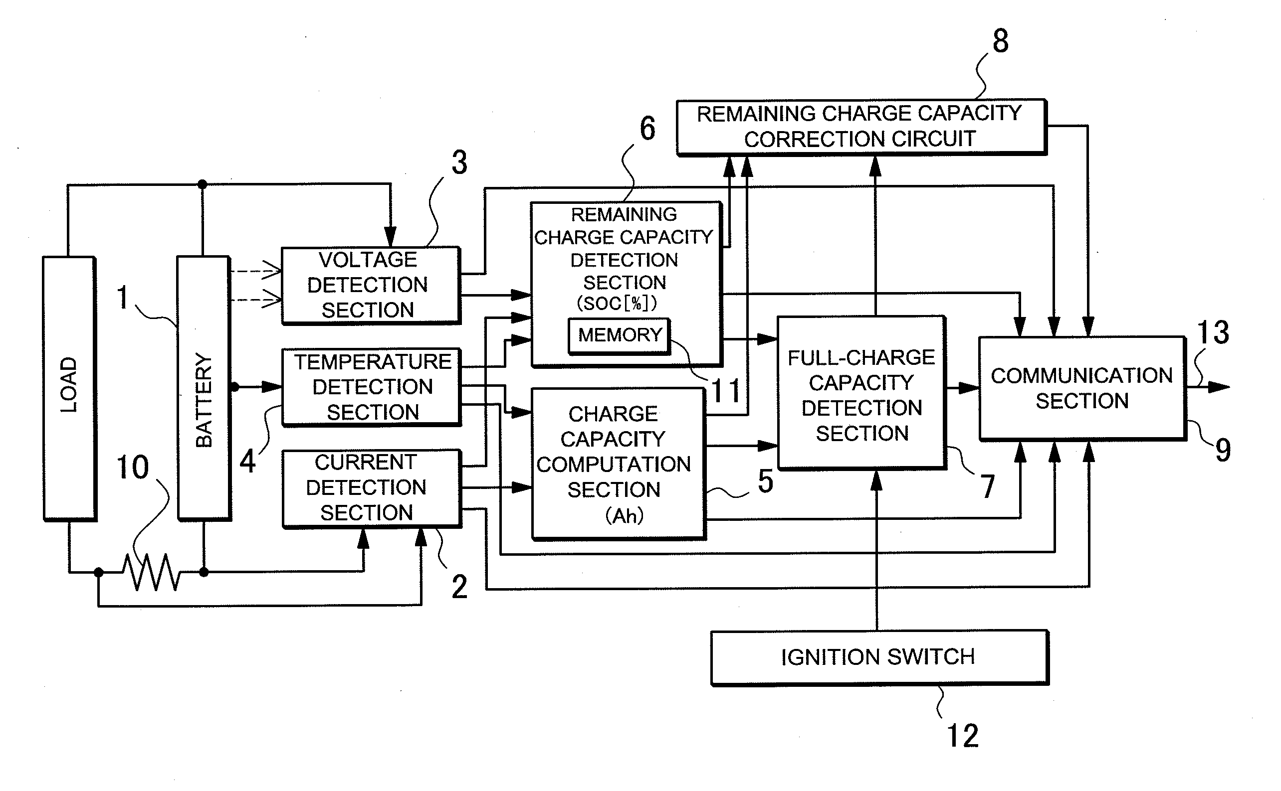
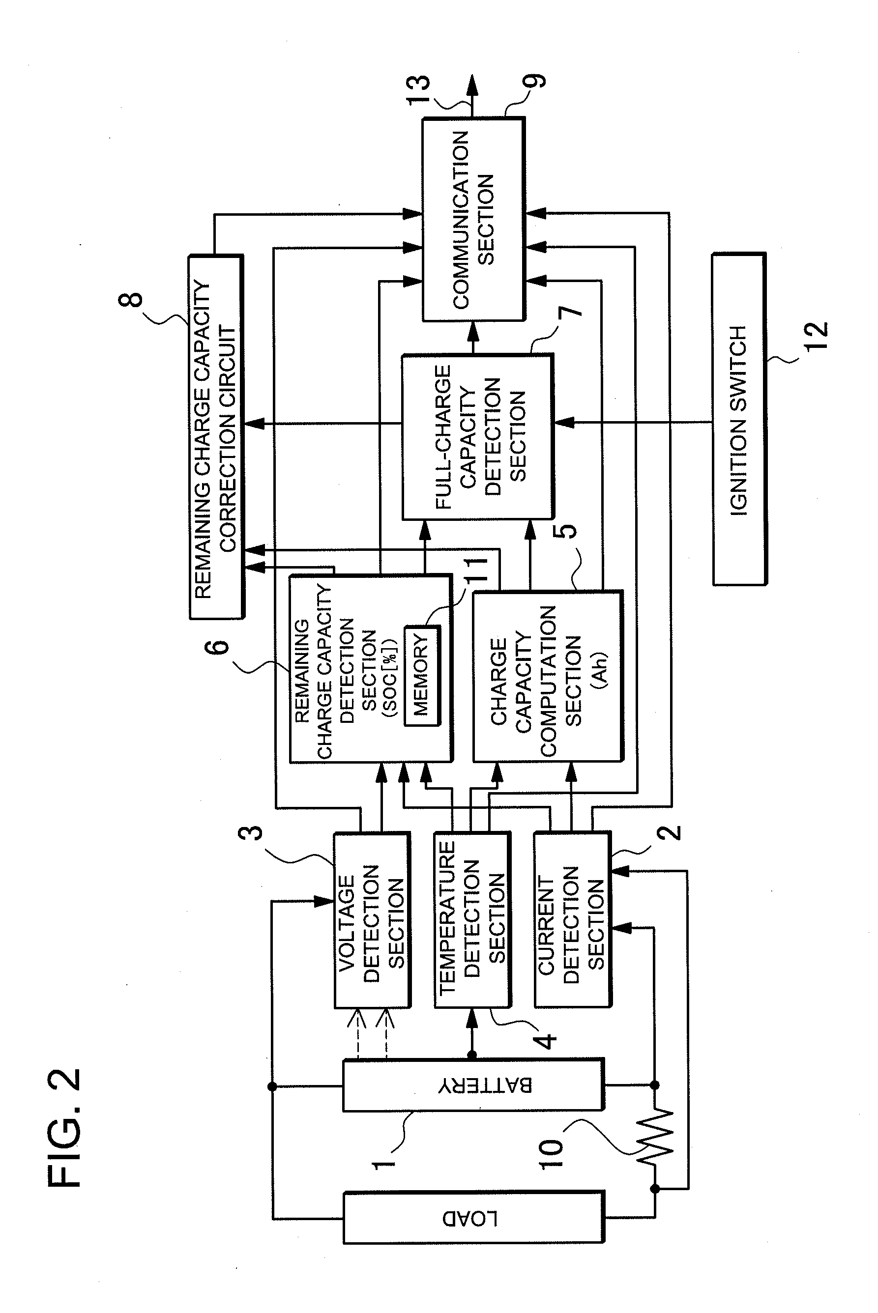
[0050]FIG. 2 is a circuit diagram of a power source apparatus used in the method of detecting battery full-charge capacity of the present invention. This power source apparatus is used to supply power to a motor and drive a vehicle, or is charged by solar cells during the daytime and used to output the stored power during either the daytime or nighttime. The power source apparatus is provided with a battery 1 that can be charged, a current detection section 2 that detects battery...


PUM


Abstract

A method including a remaining charge capacity determination step to determine a first remaining charge capacity from the first open circuit voltage and a second remaining charge capacity from the second open circuit voltage, a change in remaining charge capacity computation step to compute the change in remaining charge capacity from the difference between the first remaining charge capacity and the second remaining charge capacity, and a full-charge capacity computation step to compute the battery full-charge capacity from the change in remaining charge capacity and the change in charge capacity. The method computes battery full-charge capacity from the change in charge capacity and the change in remaining charge capacity when at least one of the values, namely the change in charge capacity, the change in remaining charge capacity, and the difference between the first open circuit voltage and the second open circuit voltage, is greater than a preset value.

Description

BACKGROUND OF THE INVENTION[0001]1. Field of the Invention[0002]The present invention relates to a method of detecting battery full-charge capacity for a battery with an actual full-charge capacity that decreases over time as the battery is charged and discharged.[0003]2. Description of the Related Art[0004]The actual full-charge capacity (Ampere-hours at full-charge, [Ahf]) to which a battery can be charged decreases over time as charging and discharging are repeatedly performed. Full-charge capacity (Ahf) is the charge capacity obtained from a fully-charged battery that is discharged to a state of complete discharge. Since batteries have the property that over-charging and over-discharging result in marked degradation, operation within a defined range of remaining charge capacity (state-of-charge, SOC [%]), which is a percent of the full-charge capacity (Ahf), can limit degradation. For this reason, accurate detection of the full-charge capacity (Ahf), which decays over time, is i...

Claims


Application Information

Patent Timeline
Patent Type & Authority Applications(United States)
IPC IPC(8): G01R31/36
CPCG01R31/36H01M10/44H01M10/48H01M2220/20G01R31/367G01R31/3828Y02E60/10
Inventor TAMEZANE, SHIGETO
Owner SANYO ELECTRIC CO LTD
Learn More