Plastic Stay-In-Place Concrete Forming System

a technology of concrete forming system and plastic cover, which is applied in the direction of auxilary members of forms/shuttering/falseworks, building repairs, walls, etc., can solve the problems of unsightly loose or flimsy plastic cover, loose and flimsy plastic cover, and inadequate structural connection of foam between concrete members, etc., to reduce the hydrostatic pressure of concr

Inactive Publication Date: 2013-11-28
KREIZINGER KENNETH ROBERT
View PDF6 Cites 28 Cited by
  • Summary
  • Abstract
  • Description
  • Claims
  • Application Information

AI Technical Summary

Benefits of technology

[0023]The invention also discloses plastic forms used in conjunction with a method of reducing the concrete...

Problems solved by technology

The foam forms must also be covered to provide an aesthetically pleasing finished appearance and the foam provides an inadequate base for structural connections between concrete members or to facilitate cladding materials.
However, these plastic sheets that comprise the forms do not attach or otherwise bond to the concrete cast inside the form.
The plastic forms only enclose the concrete and since all concrete shrinks as it cures the concrete pulls away from the plastic form which results in a loose and flimsy plastic covering.
Such a loose or flimsy covering is not only unsightly; it also inhibits the attachment of cladding materials to the exterior of the plastic form.
These thicker forms and large number of lateral connectors/webs substantially increases the amount of plastic material needed for a s...

Method used


Image

  • Plastic Stay-In-Place Concrete Forming System
  • Plastic Stay-In-Place Concrete Forming System
  • Plastic Stay-In-Place Concrete Forming System

Examples


Embodiment Construction

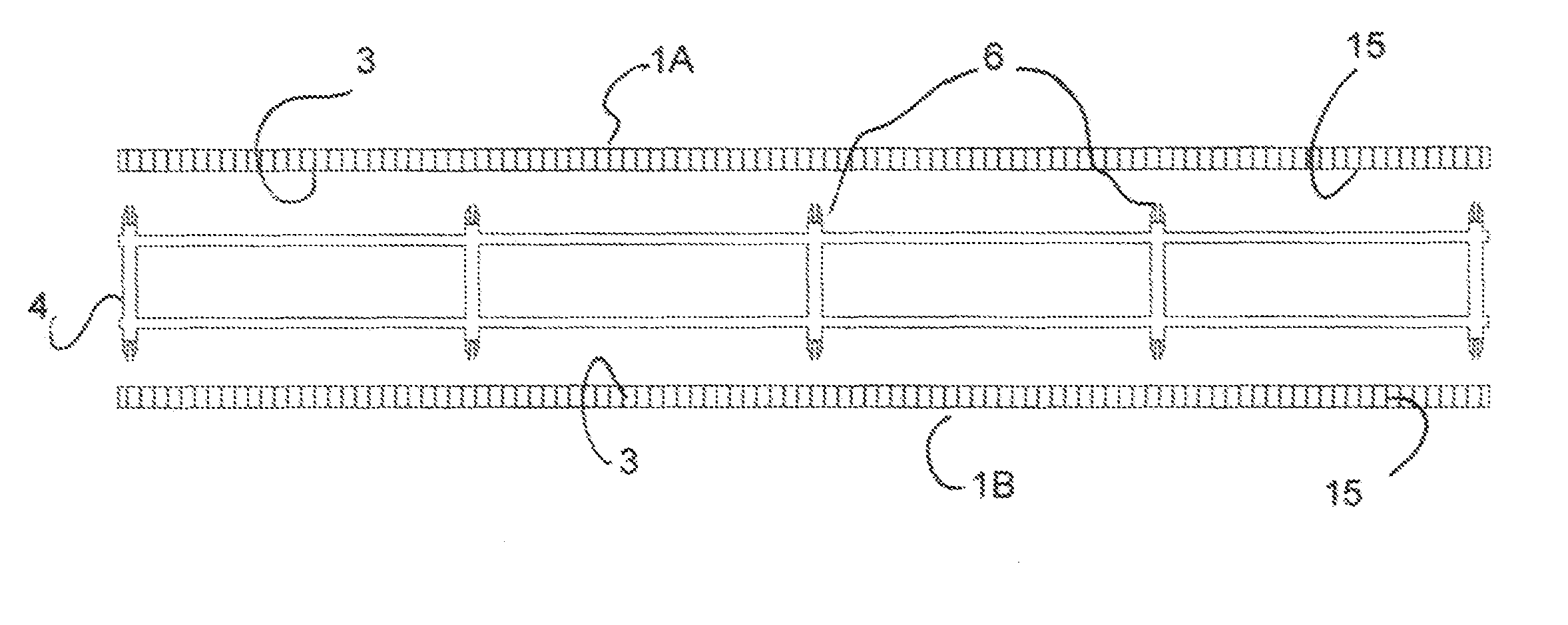
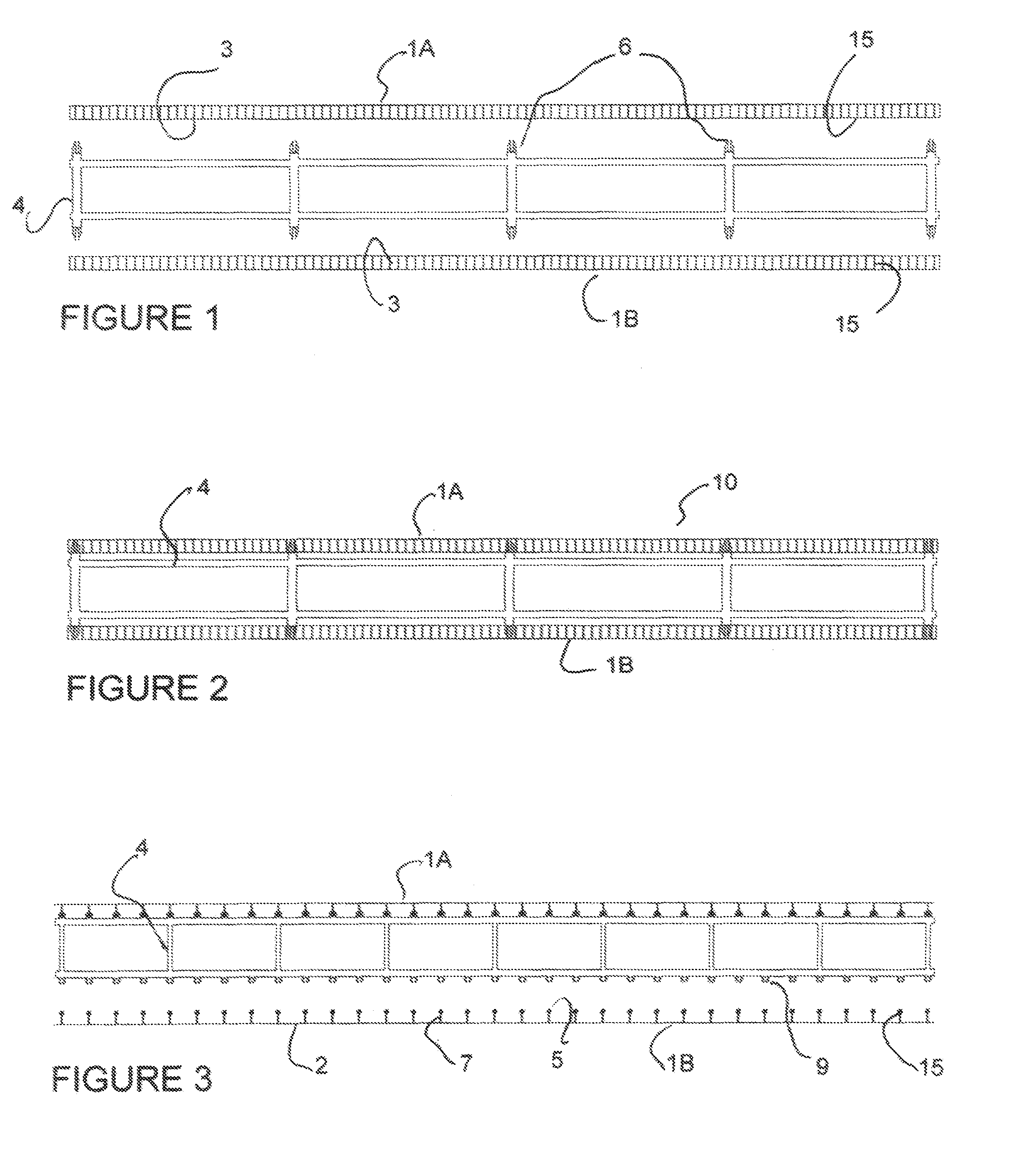
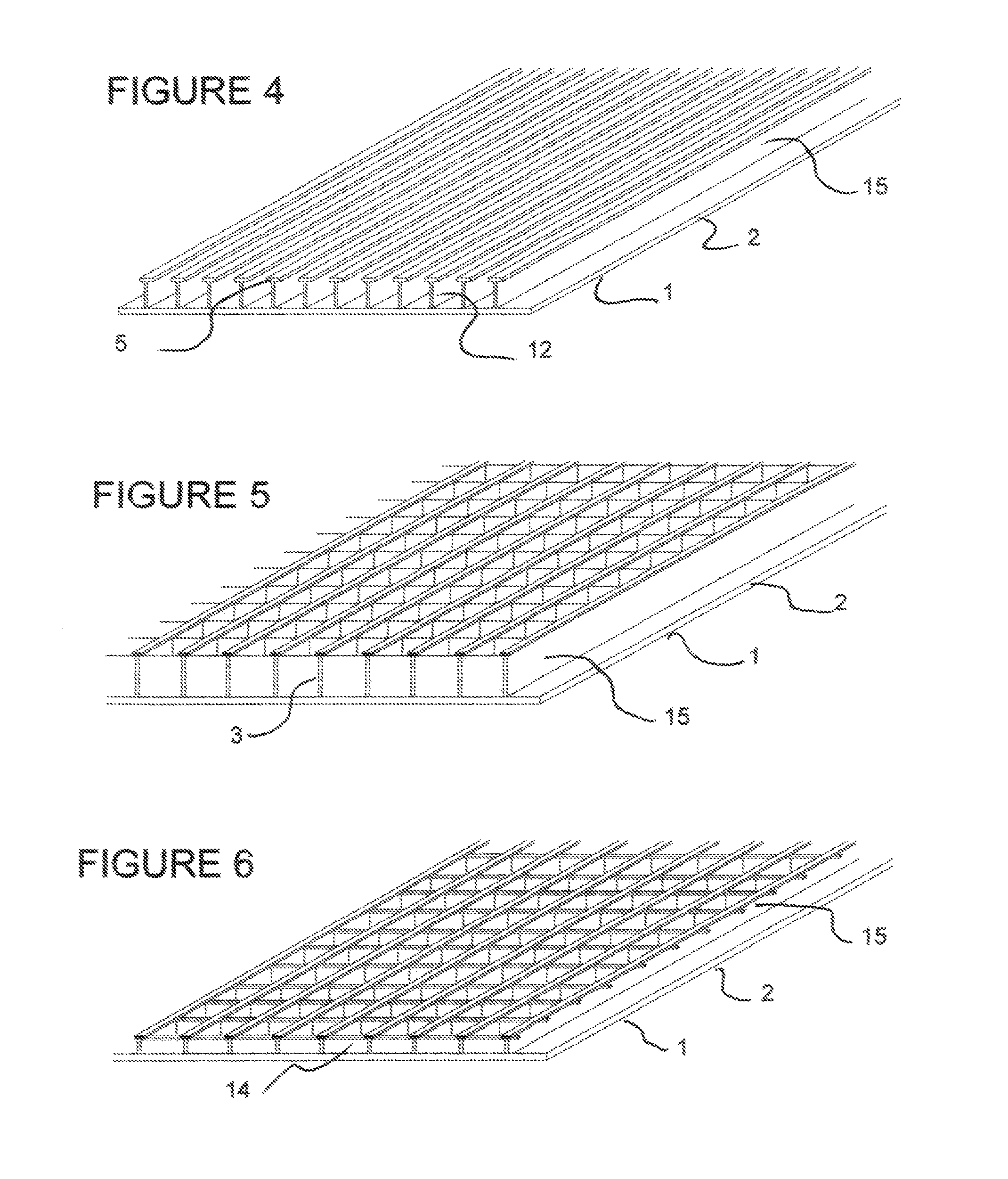
[0069]This invention concerns the use of plastic form panels as stay-in-place forms that may be used to form at least one side of a multi-sided concrete form. The plastic form panels are made from a thin plastic sheet that may be pliable and is reinforced on one or both sides. The term pliable shall mean the plastic sheet can be at least partially rolled up to form at least a quarter circle. As such, the form panels referred to in the invention include the plastic sheet that is at least partially stiffened by reinforcement permanently fabricated onto one or both sides of the plastic sheet. The form panels may have a single sheet of plastic material of any thickness or it may have composite or layered sheets or strips, with or without filler and / or backing materials on the interior and / or the exterior side of the plastic sheet. Such a filler and / or backing material may be for insulation, to achieve fire ratings, to provide a finished appearance or for other reasons that make the form...


PUM

PropertyMeasurementUnit
Hydrostatic pressureaaaaaaaaaa

Abstract

A plastic stay-in-place concrete forming system used for one or more sides of a multi-sided form and is based upon a form panel comprised of a thin plastic sheet reinforced on its interior side and capable of bonding to the concrete cast inside the form to create a solid composite structure. In one configuration the form panels are connected to internal bracing that connects to a second form side. The internal bracing is comprised of plastic connecting frames, lateral supports or individual connectors that may further reinforce the form panels or may be used solely for connecting purposes. The second side form may be any type of form including the form panel or a stud supporting foam board. The form panel may also be shaped to form two or more sides of an internally braced, multi-sided form. It may also be externally braced on one or more sides of a form.

Description

CROSS REFERENCE TO RELATED APPLICATIONS[0001]This application is a continuation-in-part of application Ser. No. 12 / 927,379 filed Nov. 12, 2010 which claims the benefit of the filing date of provisional application Nos. 41 / 281,166 and 41 / 281.121 both filed Nov. 13, 2009. This application claims the benefit of copending application Ser. No. 13 / 374,839 filed Jan. 17, 2012 claiming the benefit of the filing date of provisional application Nos. 61 / 461,437 filed Jan. 18, 2011 and 61 / 462,463 filed Feb. 3, 2011. All the above cited applications are incorporated herein by reference.BACKGROUND OF THE INVENTIONPrior Art[0002]The following is a tabulation of some prior art that presently appears relevant:U.S. Patents[0003]Patent NumberKind CodeIssue DatePatentee7,146,773B22006 Dec. 12Wilson6,247,280B12001 Jun. 19Grinshpun et al.6,167,669B12001 Jan. 2Lane5,974,7511999 Nov. 2De Zen5,729,9441998 Mar. 24De Zen5,706,6201998 Jan. 13De Zen5,092,0931992 Mar. 3Lu4,876,0541989 Oct. 24Goodwin3,238,6841963...

Claims


Application Information

Patent Timeline
IPC IPC(8): E04G11/00E04G17/00
CPCE04G11/00E04G17/00E04B5/32E04B1/161E04B2/8641E04B2/8647E04C3/34E04C5/168E04C5/20
Inventor KREIZINGER, KENNETH ROBERT
Owner KREIZINGER KENNETH ROBERT
Why Eureka
Try Eureka