Igniting an underground coal seam in an underground coal gasification process, ucg

a coal gasification process and underground coal seam technology, applied in the direction of combustible gas production, fluid removal, insulation, etc., can solve the problems of teb or silane use, high cost and time consumption, and inability to produce combustion fronts at combustion zones

Inactive Publication Date: 2013-11-28
LINC ENERGY
View PDF31 Cites 24 Cited by
  • Summary
  • Abstract
  • Description
  • Claims
  • Application Information

AI Technical Summary

Benefits of technology

[0008]It is an object of the present invention to provide a method or apparatus for igniting (or re-igniting) coal of an underground coal seam in a safe and / or cost effective manner, or to provide the public with a useful or commercial choice.

Problems solved by technology

One of the major challenges for UCG is to ignite the coal underground, particularly in a safe and cost effective manner.
One problem associated with UCG is that a combustion front produced at a combustion zone does not always progress along a coal seam as proposed in theory, and practically a coal seam may need to be reignited at different sites along the coal seam so as to maximise the production and life of the coal gasifier.
One of the problems associated with UCG when employing a well channel that extends substantially horizontally through the coal seam is that more than one vertically extending ignition well (bore hole) may be required in order to ignite / re-ignite the coal seam / gasifier at multiple locations, as installing ignition wells is an expensive and time consuming process.
In addition, the use of TEB or silane can be dangerous for handlers due to the highly volatile nature of the material when exposed to air and any mistake in handling such materials can expose them to air and initiate fire or explosion events.

Method used


Image

  • Igniting an underground coal seam in an underground coal gasification process, ucg
  • Igniting an underground coal seam in an underground coal gasification process, ucg
  • Igniting an underground coal seam in an underground coal gasification process, ucg

Examples


Embodiment Construction

[0082]In the figures, like reference numerals refer to like features.

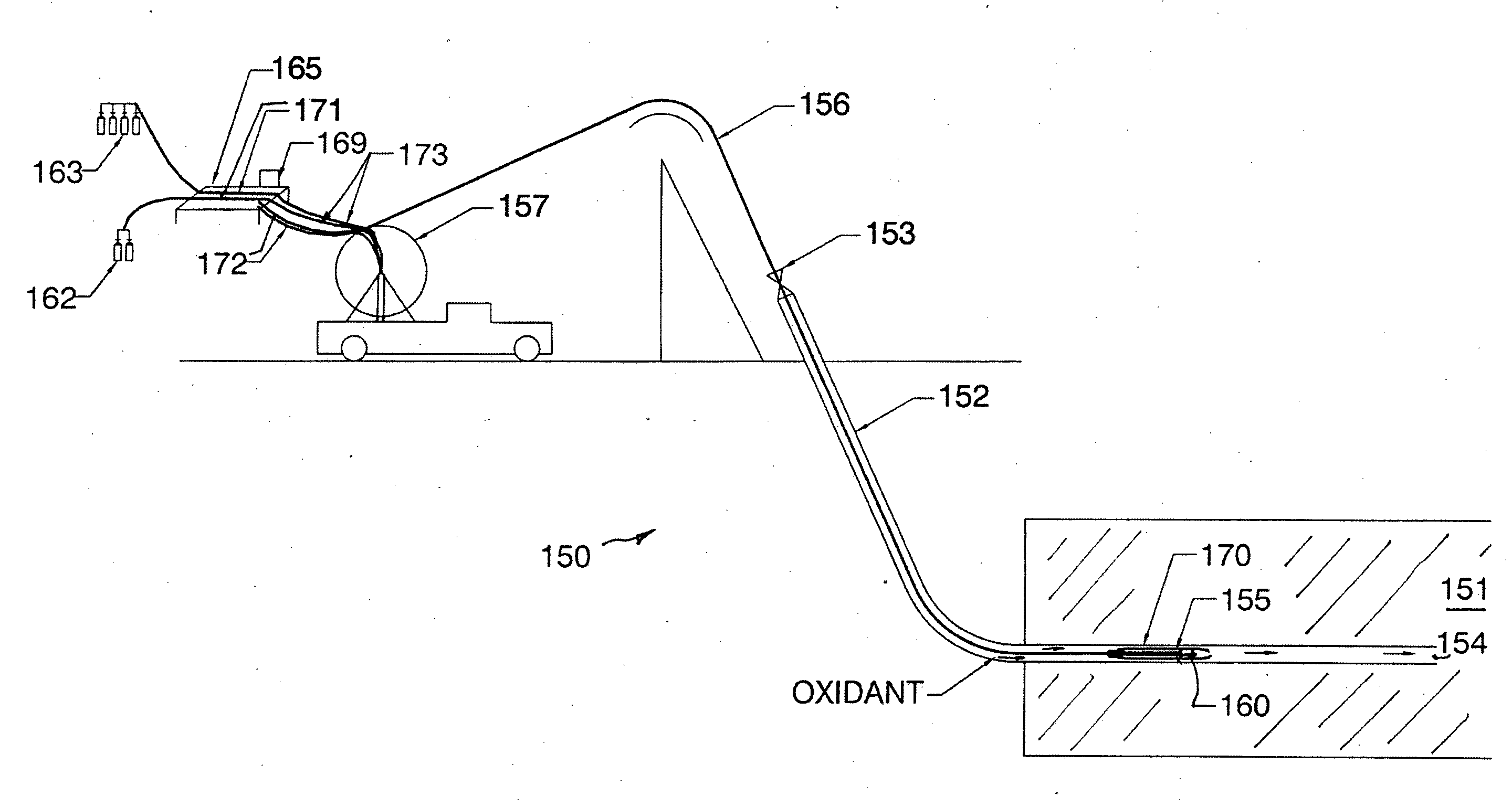
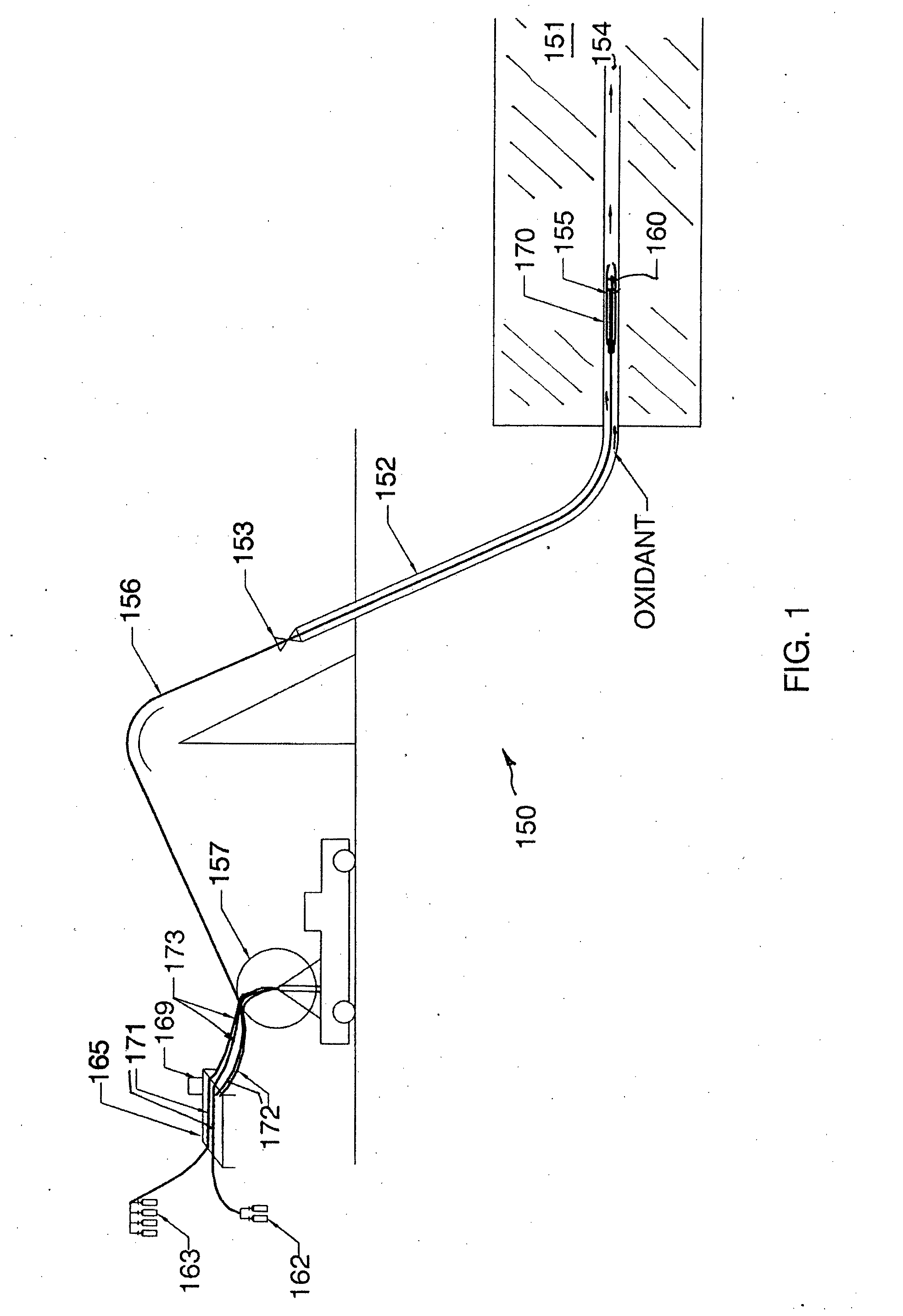
[0083]Referring first to FIG. 1, there is generally depicted an ignition apparatus 150 configured to ignite an underground coal seam 151. There is shown an injection well 152 having a well head 153 and a well channel 154 extending from a heel of the well 152 through the coal seam 151.

[0084]The ignition apparatus 150 comprising an ignition system, a positioning system, a sensor 170 and a controller 165.

[0085]The ignition system comprises ignition means and an ignition tool 155 for igniting the underground coal seam 151 from within the well channel 154 (or well liner encasing the well channel 154).

[0086]The positioning system comprises coiled tubing 156 connected to the ignition tool 155 and extendible through the well head 153 within the well channel 154 to position the ignition tool 155 at a desired location within the well channel 154. The positioning system further comprises a spool 157 for transporting and dispe...


PUM


Abstract

An ignition apparatus (150) configured to ignite an underground coal seam (151). The ignition apparatus (150) comprising an ignition system, a positioning system, a sensor (170) and a controller (165). The ignition system comprises ignition means and an ignition tool (155) for igniting the underground coal seam (151) from within the well channel (154) or well liner encasing the well channel (154). The positioning system comprises coiled tubing (156) connected to the ignition tool (155) and extendible through a well head (153) within the well channel (154) to position the ignition tool (155) at a desired location within the well channel (154). The positioning system further comprises a spool (157) for transporting and dispensing the coiled tubing (156).

Description

FIELD OF THE INVENTION[0001]This invention relates to a method and apparatus for igniting an underground coal seam, for in-situ conversion of coal to product gas.BACKGROUND OF THE INVENTION[0002]Underground coal gasification (UCG) is a process by which product gas is produced from a coal seam by heating the coal in situ in the presence of an oxidant. The product gas is typically referred to as synthesis gas or syngas and can be used as a feedstock for electricity or chemical production, for example.[0003]Conversion of coal into product gas takes place in a well which typically includes a well channel of sorts extending through the coal seam. Such a channel can be formed by one or more bore holes drilled into the coal seam that are in fluid communication with one another. The channel is also in fluid communication with an injection well, a production well as well as perhaps one or more ignition or service wells that extend from ground level to the well channel. Typically, oxidant is ...

Claims


Application Information

Patent Timeline
Patent Type & Authority Applications(United States)
IPC IPC(8): E21B43/243
CPCE21B43/243C10J3/18E21B43/295
Inventor SHAIKH, FAZAL UDDINBURGER, CASPER JAN HENDRIKPERKINS, GREG MARTIN PARRY
Owner LINC ENERGY
Why Eureka
Try Eureka