

Duty cycle corrector
- Summary
- Abstract
- Description
- Claims
- Application Information
AI Technical Summary
Benefits of technology
Problems solved by technology
Method used
Image

Examples
Embodiment Construction
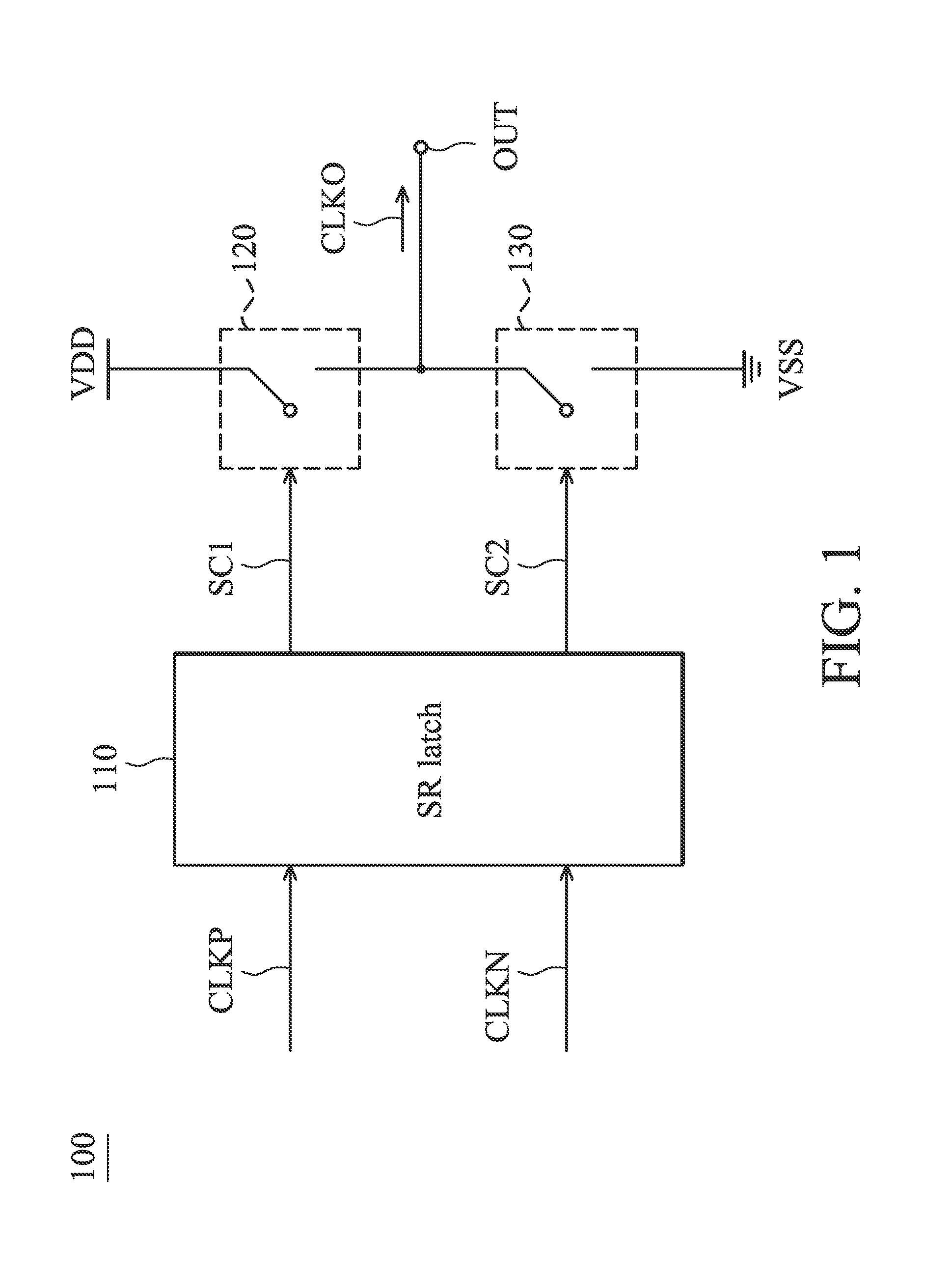
[0015]FIG. 1 is a diagram for illustrating a duty cycle corrector 100 according to an embodiment of the invention. As shown in FIG. 1, the duty cycle corrector 100 comprises an SR latch 110, and two switches 120 and 130. The SR latch 110 generates two control signals SC1 and SC2 according to a clock CLKP and another clock CLKN. In an embodiment, the SR latch 110 has a set input terminal for receiving the clock CLKP, and a reset input terminal for receiving the clock CLKN. In another embodiment, the SR latch 110 has the reset input terminal for receiving the clock CLKP, and the set input terminal for receiving the clock CLKN. The switch 120 is coupled between a work voltage VDD and an output node OUT, and selectively closes and opens according to the control signal SC1. Similarly, the switch 130 is coupled between the output node OUT and a ground voltage VSS, and selectively closes and opens according to the control signal SC2. The output node OUT is used to output an output clock CL...
PUM
 Abstract
Description
Claims
Application Information