Indicator member, indicator unit and indicator instrument

a technology of indicator parts and indicators, applied in the field of indicators, can solve the problems of increasing the manufacturing cost of indicators, increasing the number of components, increasing the man-hour for assembly, etc., and achieve the effects of preventing non-uniform brightness, and reducing the risk of affecting the quality of indicators

Inactive Publication Date: 2013-11-28
YAZAKI CORP
View PDF0 Cites 19 Cited by
  • Summary
  • Abstract
  • Description
  • Claims
  • Application Information

AI Technical Summary

Benefits of technology

[0067](1.5)According to the invention described in the first to fifth aspects, the reflection part provided at the indicator part of the indicator member includes the plurality of partial reflection parts including at least the pointing direction reflection face, the rear end direction reflection face and the corner formed at the intersection of the pointing direction reflection face and the rear end direction reflection face and arranged at the location opposed to the base part, wherein the corners of the respective partial reflection parts located adjacent to each other are displaced in the pointing direction or the rear end direction. Thus, the corners at which the brightness of the light transmitted through the pointing direction reflection face or the rear end direction reflection face are not concentrated at one location but are dispersed in the pointing direction and in the rear end direction. Therefore, even if the corner of one of the partial reflection parts is arranged toward the rear end direction to reflect more light toward the pointing direction, the corners of the other ones of the partial reflection parts are displaced toward the pointing direction so as to be placed near the end at the pointing direction side and the end at the rear end direction side of an upper region of the reflection part. Therefore, the brightness near the both ends of this region can be maintained, thereby preventing a dark area from being formed at a location above the reflection part at a low cost without providing a light diffusing member or the like.
[0068]According to the invention described in the second aspect, the reflection part is formed symmetric about the widthwise center of the indicator part, thereby preventing non-uniformity in the brightness in the widthwise direction.
[0069](2.5)According to the invention described in the sixth to eighth aspects, the hollow reflection part provided at the indicator part of the indicator member includes the pointing direction reflection face, the rear end direction reflection face and the transmission face, and this transmission face is formed into the convexly curved surface which is convex toward the upper face of the indicator part from one end connected to the pointing direction reflection face to another end connected to the rear end direction reflection face. Thus, for the light which has transmitted through each of the pointing direction reflection face and the rear end direction reflection face, the incidence angle of this light with respect to the transmission face is adjusted such that the light is refracted so that the spread angle of the light which has entered the transmission face is increased compared to said spread angle in the case of the transmission face formed into the flat surface. Therefore, by adjusting the shape of the transmission face and optimizing the spread angle of the light can prevent the dark area from being formed near the location at the upper face of the indicator part and at the extension of the pointing direction reflection face and the rear end direction reflection face, thereby preventing non-uniformity in the brightness at the upper face of the indicator part at a low cost without providing a light diffusing member or the like.
[0070](3.5)According to the invention described in the ninth to eleventh aspects, the indicator member includes the notch provided at the bottom face of the pointing part facing the base part, and the notch includes the upward reflection face which reflects the light reflected by the pointing direction reflection face toward the section of the upper face of the pointing part at opposite side of the bottom face, the section being adjacent to the hollow reflection part. Thus, without making the pointing part to be thin since the notch is formed into the notched shape, the light reflected by the pointing direction reflection face can be reflected toward the upper face of the pointing part by the upward reflection face of the notch. Thus, the amount of light exiting from said section can be increased, thereby preventing the dark area from being formed at said section and preventing the non-uniformity in the brightness at the upper face of the indicator part.
[0071](4.5)According to the invention described in the twelfth aspect, the reflection part for indicator shaft is formed continuously from the base part to the pointing part so as to reflect the light heading from the indicator shaft fixed to the shaft receiving part of the base part to the outside of the base part toward the upper face of the pointing part adjacent to the pointing direction reflection face. Thus, the light leaking from the base part to the outside of the indicator member can be reduced, and this light can be guided toward the upper face of the pointing part near the end of the pointing direction reflection face, thereby preventing the dark area from being formed at the upper face of the pointing part. Therefore, the non-uniformity in the brightness at the upper face (i.e. the light-emitting face) of the indicator member can be prevented, and the lighting quality can be improved. Furthermore, since there is no need to provide the light diffusing component for preventing the dark area from being formed at the upper face of the pointing part at the pointing direction reflection face, the number of components can be reduced, thereby reducing the cost of the indicator member.
[0072]In addition to the effect of the invention of the twelfth aspect, according to the invention described in the thirteenth aspect, the reflection part for indicator shaft includes the light guard part and the reflection face for indicator shaft, thus the light heading from the indicator shaft to the outside of the pointing part can be guided by the light guard part toward the pointing part and the reflection face for indicator shaft. Thus, the light leaking from the base part to the outside of the indicator member can be reduced even more.

Problems solved by technology

However, there is a problem that, when the light diffusing component and the filter member and such are provided to prevent the formation of the dark area D at the section R of the upper face 953 of the indicator part 950 located above the hollow reflection part 960 as described above, the number of components is increased and the man-hour for assembling is increased as well, causing an increase in the manufacturing cost of the indicator member.

Method used


Image

  • Indicator member, indicator unit and indicator instrument
  • Indicator member, indicator unit and indicator instrument
  • Indicator member, indicator unit and indicator instrument

Examples


Embodiment Construction

[0242](1.8)

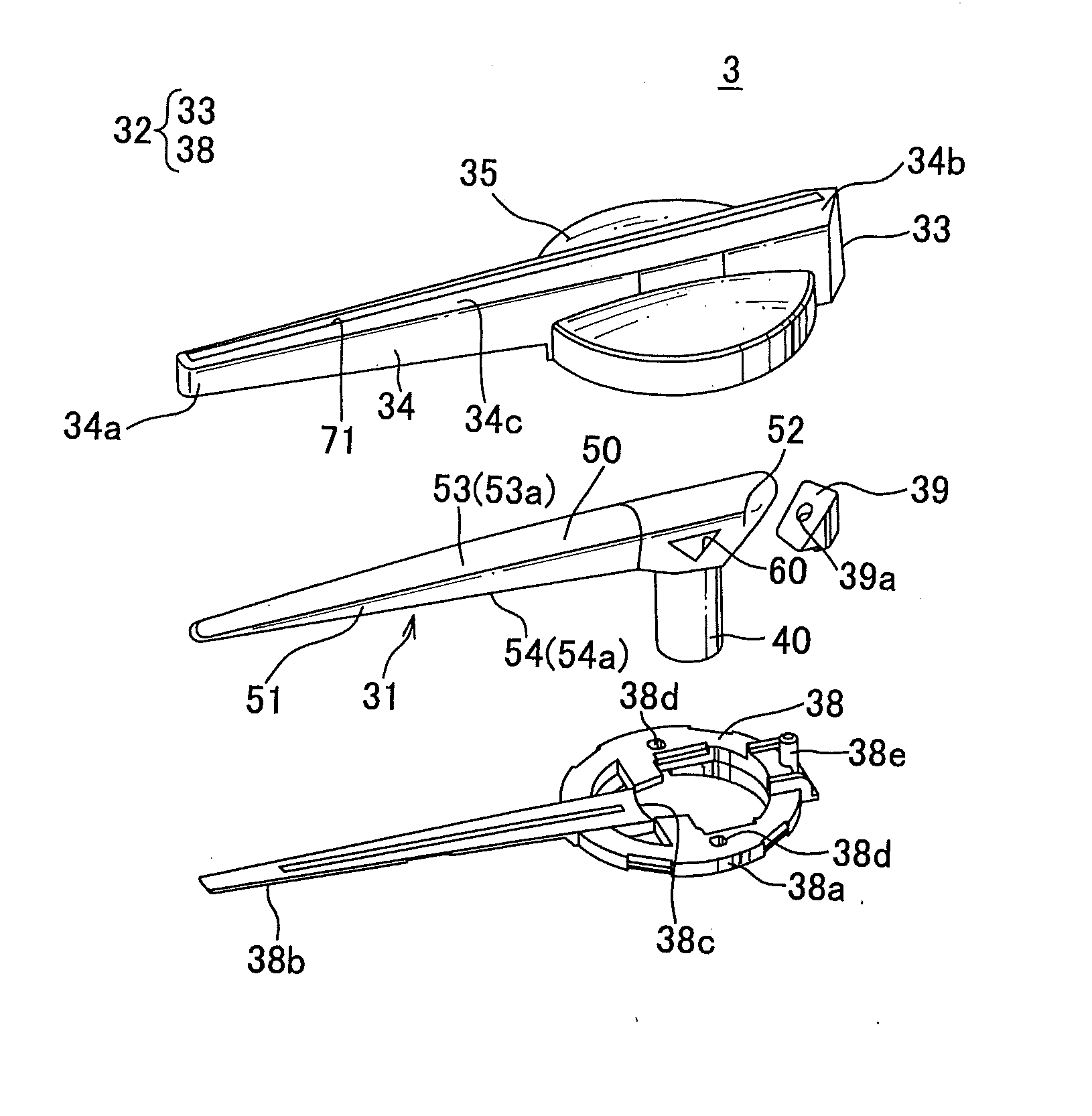
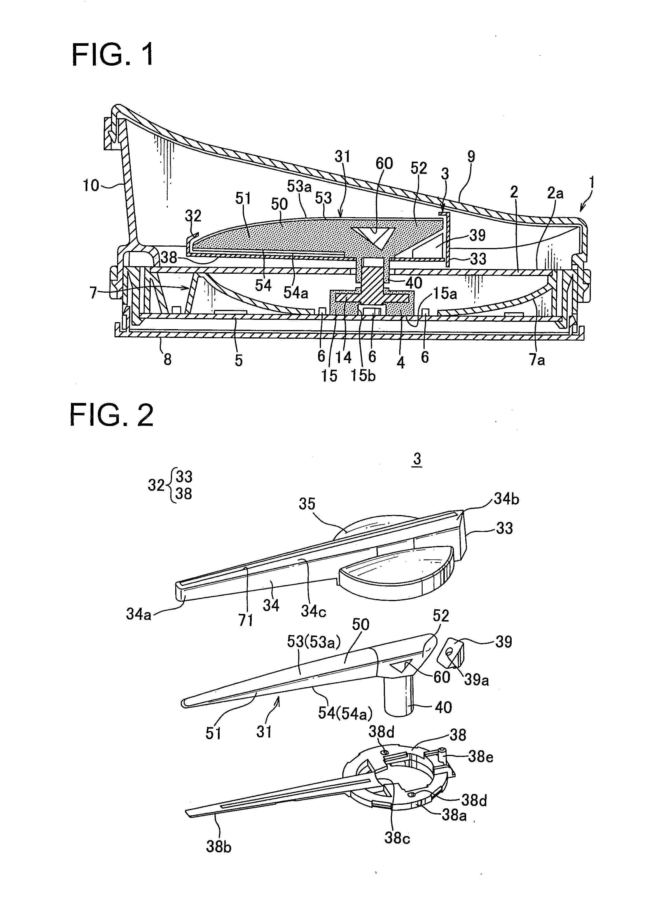
In the following, a vehicle display device as one embodiment of an indicator instrument according to the present invention is explained in reference to FIGS. 1 through 4B.

[0243]In FIG. 1, a vehicle display device 1 is a speed meter which displays a vehicle speed, for example. The vehicle display device 1 includes a dial plate 2 having a surface 2a (i.e. a surface which is visible by a viewer) provided with indexes such as scale marks and numbers, letters or symbols, a light-emitting indicator (hereinafter called an indicator) 3 as an indicator unit positioned on the surface 2a of the dial plate 2, a drive device 4 having an indicator shaft 14 including a distal end at which the indicator 3 is attached, a circuit board 5 including a circuit pattern, an electronic component and such and including the drive device 4 fixed to the circuit board 5, a plurality of light sources 6 provided at the circuit board 5, a case 7 having a tapered portion 7a formed from a central portion ...


PUM


Abstract

[Problem to be solved] To provide an inexpensive indicator member which can prevent a dark area from being formed at a location above a reflection part, an indicator unit having the indicator member and an indicator instrument having the indicator unit.[Solution to Problem] A hollow reflection part provided to an indicator part of an indicator main body of a light-emitting indicator includes a plurality of partial reflection parts having at least an pointing direction reflection face, a rear end direction reflection face and a corner formed at an intersection of the pointing direction reflection face and the rear end direction reflection face and arranged at a location opposed to the base part. The corners of the respective partial reflection parts adjacent to each other are displaced in a pointing direction or in a rear end direction.

Description

TECHNICAL FIELD[0001](1.1), (2.1), (3.1)The present invention relates to an indicator member made of translucent material which becomes luminous by receiving the light from a light source, an indicator unit having said indicator member and an indicator instrument having said indicator unit.[0002](4.1)The present invention relates to an indicator member arranged to guide the light from a translucent indicator shaft to be luminous, an indicator unit having said indicator member and an indicator instrument having said indicator unit.BACKGROUND ART[0003](1.2)In general, a vehicle is mounted with a vehicle display device arranged to display a measured value such as vehicle speed and engine revolution number, and in many vehicles said vehicle display device is constituted of an indicator instrument. The indicator instrument includes a meter case which houses a dial plate having a surface provided with indexes such as scale marks and numbers, letters or symbols, an indicator unit positione...

Claims


Application Information

Patent Timeline
Patent Type & Authority Applications(United States)
IPC IPC(8): G01D13/22
CPCG01D13/22B60K35/00B60Q3/62B60K2370/20B60K2370/33B60K2370/6992B60K2370/27G01D13/265F21V7/00F21W2111/00G02B6/0055
Inventor MIYAZAWA, TOMOHIROOGAWA, MASAYUKI
Owner YAZAKI CORP
Why Eureka
Try Eureka