Method for partial lamination of flexible substrates

a flexible substrate and lamination technology, applied in lamination, ancillary operations, chemistry apparatus and processes, etc., can solve the problems of high equipment requirements and very high precision in the implementation of the method, deformation of the film/foil laminate, and detachment of the two film/foil webs from each other, and achieve the effect of simple process

Inactive Publication Date: 2013-11-28
HERAEUS PRECIOUS METALS GMBH & CO KG
View PDF4 Cites 7 Cited by
  • Summary
  • Abstract
  • Description
  • Claims
  • Application Information

AI Technical Summary

Benefits of technology

[0040]The invention is based on the surprising finding that punch-lamination can proceed in a single step. This is advantageous in that a simple process is thus enabled. The device needed for implementing the method preferably needs just one central punching-laminating tool. As a result, the films/foils can even have different conveying directions, since it is feasible according to an embodiment of the present invention to let the entire punch-lamination proceed at a single site only.
[0041]Especially the alignment of the tool with respect to th

Problems solved by technology

Moreover, it is associated with a problem related to firmly connecting two film/foil webs to each other under such starting conditions, because thermo-mechanical tension between the two film/foil webs arises in this type of film/foil laminate once the tensile force is released or after equilibration of the temperatures of the two film/foil webs is reached, thereby possibly leading to deformation of

Method used


Image

  • Method for partial lamination of flexible substrates
  • Method for partial lamination of flexible substrates
  • Method for partial lamination of flexible substrates

Examples


Embodiment Construction

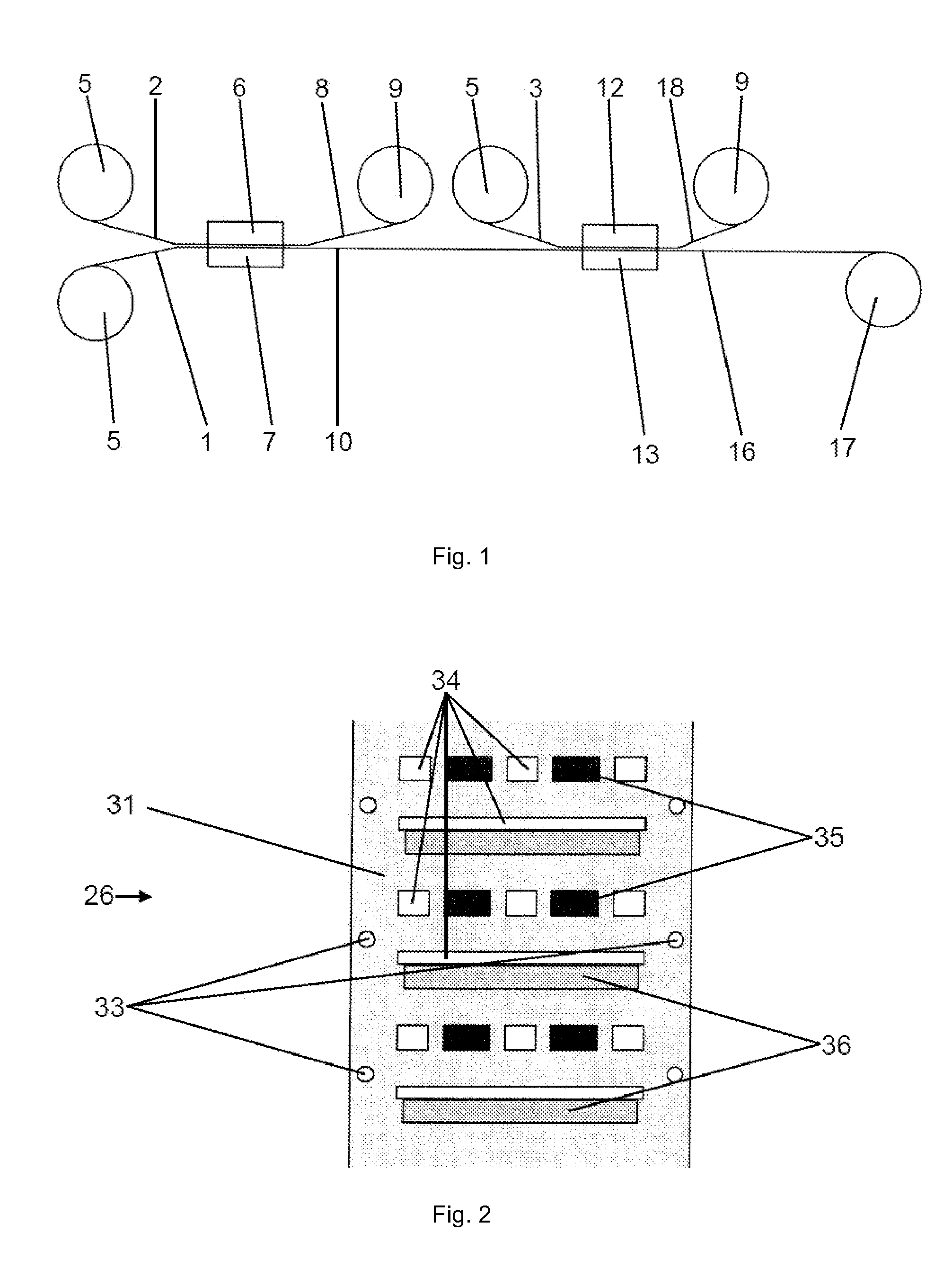
[0049]FIG. 1 shows a schematic cross-sectional view of a first device according to an embodiment of the invention for producing a laminate. A first film / foil 1, a second film / foil 2, and a third film / foil 3 are fed to the device. The films / foils 1, 2, 3 are reeled-up on rolls 5 and are unreeled off the rolls 5 and fed to the device.

[0050]The first film / foil 1 is pre-punched and reeled-up on the lower roll 5. The first film / foil 1 and the second film / foil 2 are unreeled and fed to the device. For this purpose, the films / foils 1, 2 are redirected in appropriate manner, such that they are guided to be parallel in a first region at a distance of approximately 5 mm. A first tool 6 of the device is arranged in the first region. The tool 6 comprises a heatable base surface 7 over which the first film / foil 1 runs.

[0051]In the region of the tool 6, the second film / foil 2 is applied onto the first film / foil 1 and is punched-out in the process. The punched-out segments of the second film / foil ...


PUM

PropertyMeasurementUnit
Timeaaaaaaaaaa
Lengthaaaaaaaaaa
Lengthaaaaaaaaaa

Abstract

A method for producing a laminate made up of at least two films/foils is provided. At least one first film/foil is structured and subsequently laminated to at least one second film/foil. The at least one second film/foil is punched by at least one tool in a single working step and is laminated to the structured first film/foil simultaneously. The films/foils are conveyed, at least part of the time, to the at least one tool. A laminate produced according to such a method and a device for producing a laminate using such a method are also provided. The device is suited for conveying and laminating the at least one first and second films/foils, wherein regions of the films/foils are aligned to be parallel with respect to each other. The device includes at least one tool that can be used to punch-laminate second film/foil onto the first film/foil.

Description

CROSS-REFERENCE TO RELATED APPLICATIONS[0001]This application is a Section 371 of International Application No. PCT / EP2012 / 000154, filed Jan. 16, 2012, which was published in the German language on Aug. 16, 2012, under International Publication No. WO 2012 / 107157 A1 and the disclosure of which is incorporated herein by reference.BACKGROUND OF THE INVENTION[0002]The invention relates to a method for producing a laminate made up of at least two films / foils, wherein at least one first film / foil is structured and subsequently laminated to at least one second film / foil.[0003]The invention also relates to a laminate produced according to the method and to a device for producing a laminate using the method.[0004]Laminates made up of two films / foils have wide applicability in industry. In this context, for example, a metal foil is laminated onto a plastic film or between two plastic films. The films / foils are structured during this process in order to obtain the desired product. It is known...

Claims


Application Information

Patent Timeline
IPC IPC(8): B32B38/00B32B38/06B32B3/10
CPCB32B38/0004B32B3/10B32B38/06B32B37/04B32B37/12B32B37/203B32B38/04B32B38/1816B32B38/185B32B2038/042B32B2311/00Y10T156/12Y10T156/1056Y10T156/1062Y10T156/1039
Inventor GRESCH, MANFREDROTH, JOSEFWALTER, SIEGFRIEDBUSCHMANN, GERDBECKER, UDO
Owner HERAEUS PRECIOUS METALS GMBH & CO KG
Why Eureka
Try Eureka