
Method for detecting cause of radio link failure or handover failure

a radio link and cause detection technology, applied in the field of mobile communication technology, can solve the problems of difficult to simply use a classification, inability to correctly understand the meaning, and failure of rlf, and achieve the effect of improving the accuracy of determining a caus

Inactive Publication Date: 2013-11-28
SAMSUNG ELECTRONICS CO LTD
View PDF6 Cites 38 Cited by
  • Summary
  • Abstract
  • Description
  • Claims
  • Application Information

AI Technical Summary

Benefits of technology

The patent text describes methods for detecting the cause of radio link failure or handover failure in mobile networks. The goal is to improve the accuracy of determining the cause so that the network can learn from the failure and improve efficiency and system performance. The methods involve sending the mobility or handover information of the failed user equipment (UE) to the target base station and analyzing it together with the RLF report to determine the cause of the failure. This helps avoid saving context information of the UE which has moved away, and ensures the correct radio link or handover configuration information is found. The methods are compatible with existing technology and improve efficiency of mobility management and performance of the mobile network.

Problems solved by technology

a) In a process that a UE is handed over from a macro cell to a pico cell, due to high speed movement of the UE, the UE fails to access a target cell, or when the UE is just successfully handed over to the target pico cell, an RLF failure occurs and the UE successfully establishes a connection in a source cell or another macro cell. For UEs moving at low speed, if it is determined that such a situation occurs to a plurality of UEs, handover triggering of the macro cell and the pico cell is needed to be adjusted. If such a situation occurs to a UE moving at high speed, it is only needed to adjust handover triggering of the UE moving at high speed.
b) In case of cell range expansion (CRE), handover criteria for UE in macro cells may be different. If the UE is just successfully handed over to the pico cell, an RLF failure occurs and the UE successfully accesses a source cell or another cell, since the handover criteria for UE in macro cells may be different, the cause of the failure may be handover too early or handover to a wrong cell; but according to the related art, after a source cell (a cell which triggers a handover to the pico cell) receives a handover report, since the source cell cannot correctly identify which handover criteria is wrong, thus, the source cell cannot correctly determine the cause of the failure.
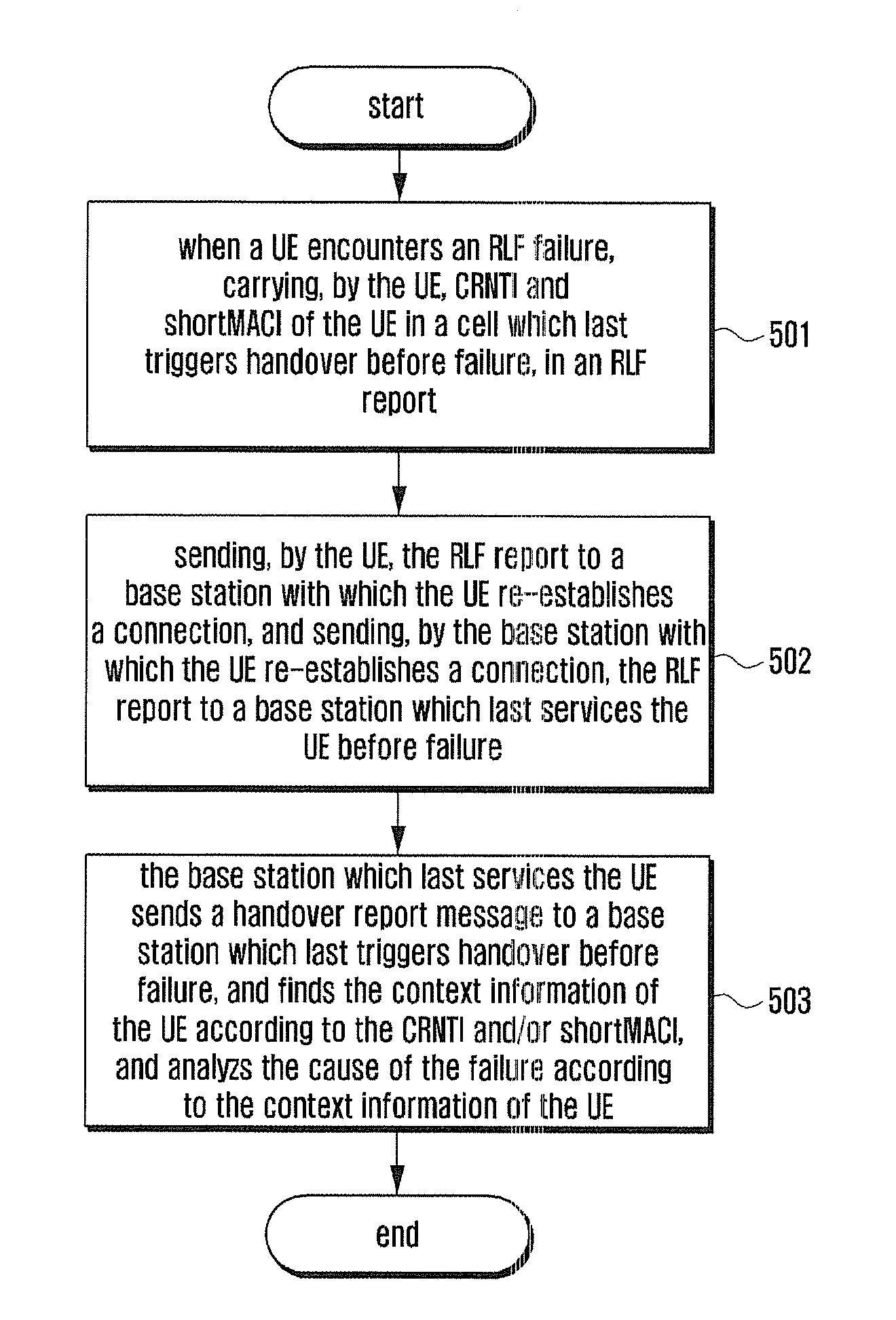
But when this method is used in a situation that a handover from a macro cell to a pico cell is successful and that an RLF failure occurs when the handover is just successful and the UE successfully establishes a connection in a source macro cell or another macro cell, since the last cell serving the UE is the pico cell, thus, the C-RNTI (Cell-Radio Network Temporary Identifier) and the shortMACI reported by the UE are information of the UE in the pico cell.
The first problem: Handover triggering needs to consider many factors, such as measurement configuration, measurement result, method for eliminating the interference, load balancing and so on; it is difficult to simply use a classification to represent a handover type, a result of a judgment based on the classification will appear error and deviation.
The second problem: According to an existing mobility robustness optimization detection method, it is a base station where a last cell serving the UE is located to determine the cause of the RLF or handover failure.
The following problem is associated with the third scheme: If the base station re-accessed by the UE is not a base station which last triggers handover, the base station re-accessed by the UE cannot correctly understand the meaning of the HO token, and thus cannot make a correct judgment.
Meanwhile, the problems in the second scheme also exist in the third scheme.
It can be seen that the related art cannot solve the problems encountered in case of the deployment of heterogeneous network (HetNet).

Method used


Image

  • Method for detecting cause of radio link failure or handover failure
  • Method for detecting cause of radio link failure or handover failure
  • Method for detecting cause of radio link failure or handover failure

Examples


first embodiment

[0112]Based on the above methods, FIG. 7 shows a flowchart of the first method for detecting a cause of Radio Link Failure (RLF) or handover failure according to the present disclosure. As shown in FIG. 7, the flow includes:

[0113]Block 701: triggering, by a base station 1, a handover process for a UE, and sending a handover request message including mobility or handover information of the UE in the source cell, to a target base station, i.e., base station 2. The mobility or handover information of the UE is the same as that of the block 301, and will not be repeated here. The base station 2 saves the mobility or handover information of the UE in a cell 1 of the base station 1 in the UE context.

[0114]Block 702: sending, by the base station 2, a handover request confirmation message to the base station 1.

[0115]Block 703: sending, by the base station 1, a handover command message to the UE.

[0116]Block 704: the UE successfully accessing a cell 2. Here, it may be that the UE sends a rand...

second embodiment

[0124]Based on the above methods, FIG. 8 shows a flowchart of the first method for detecting a cause of Radio Link Failure or handover failure according to the present disclosure. As shown in FIG. 8, the flow includes:

[0125]Block 801 to block 805 are the same as block 701 to block 705, and will not be repeated here.

[0126]Block 806: re-establishing or establishing, by the UE, an RRC connection in a cell 1 (i.e., a cell which is controlled by a base station which last triggers a handover before failure). In the process of establishment of the RRC connection, the UE indicates to the network RLF report information.

[0127]Block 807: sending, by the UE, the RLF report to a base station 1. Specifically, the base station 1 obtains information that the UE has an RLF report, and the base station 1 sends a UE information request to the UE to request for the RLF report information. The UE sends a UE information response containing the RLF report information of the UE to the base station. The RLF...


PUM


Abstract

A method for detecting a cause of radio link failure (RLF) or handover failure, in which the first base station triggers a handover process for the UE, and the mobility or handover information of the UE in the source cell is sent to a second base station. After the second base station receives the RLF report of the UE, the second base station can determine cause of a failure according to the RLF report of the UE and the mobility or handover information of the UE in the source cell. Other methods detect a cause of radio link failure (RLF) or handover failure. Application of the methods can improve the accuracy of determining the cause of the RLF or handover failure, improve efficiency of MRO and improve system performance.

Description

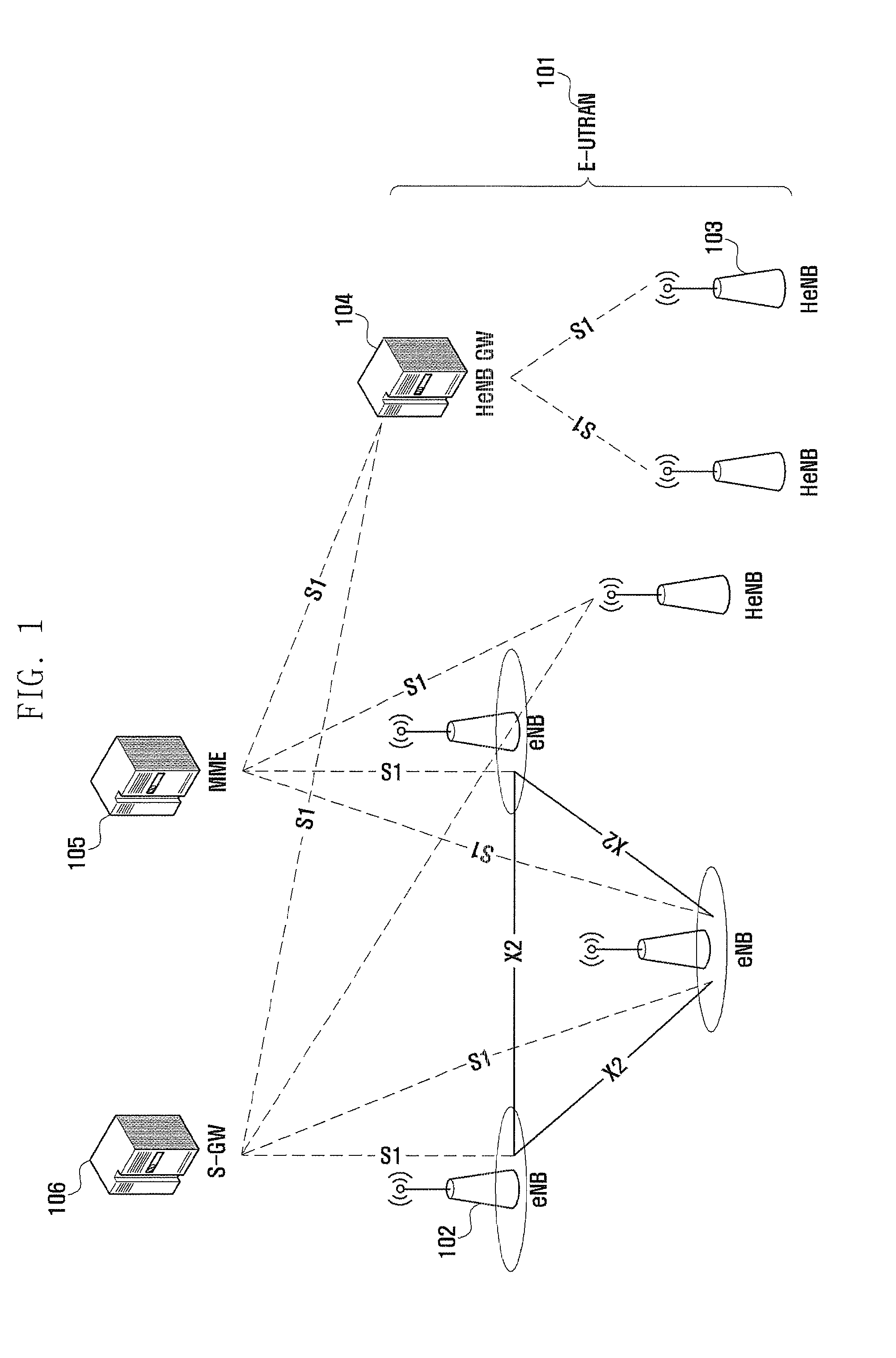
CROSS-REFERENCE TO RELATED APPLICATION(S) AND CLAIM OF PRIORITY[0001]The present application is related to and claims the benefit under 35 U.S.C. §119(a) of a Chinese patent application filed in the Chinese Intellectual Property Office on May 22, 2012 and assigned Serial No. 201210159909.2, the entire disclosure of which is hereby incorporated by reference.TECHNICAL FIELD OF THE INVENTION[0002]The present disclosure relates to mobile communication technology, and more particularly to a method for detecting a cause of radio link failure (RLF) or handover failure.BACKGROUND OF THE INVENTION[0003]Along with the development of communication technologies, the mobile communication system has evolved into a System Architecture Evolution (SAE) system. FIG. 1 is a schematic diagram illustrating a structure of a SAE system. Referring to FIG. 1, the SAE system includes an Evolved Universal Terrestrial Radio Access Network (E-UTRAN) 101 and a core network containing a Mobile Management Entity (...

Claims


Application Information

Patent Timeline
Patent Type & Authority Applications(United States)
IPC IPC(8): H04W36/32
CPCH04W36/32H04W36/0079H04W76/19H04W36/324H04W36/08H04W24/10H04W36/0033
Inventor XU, LIXIANGWANG, HONGLIANG, HUARUIKE, XIAOWAN
Owner SAMSUNG ELECTRONICS CO LTD
Learn More