Supercharge Your Innovation With Domain-Expert AI Agents!

Powertrain for a vehicle

a technology for powertrains and vehicles, applied in the direction of engine-driven generators, propulsion, transportation and packaging, etc., can solve the problems of large fuel consumption and in the wear of conventional clutch mechanisms, and large space occupation of vehicles. , to achieve the effect of simple and functional way

Active Publication Date: 2013-11-28
SCANIA CV AB
View PDF7 Cites 28 Cited by
  • Summary
  • Abstract
  • Description
  • Claims
  • Application Information

AI Technical Summary

Benefits of technology

This patent proposes a system for vehicles that lets you change the speed of the engine's input shaft as you're using the car. The technical effect of this is increased flexibility and efficiency in driving.

Problems solved by technology

There are disadvantages in using a conventional clutch mechanism which disconnects the gearbox input shaft from the engine during gearchange processes in the gearbox.
This warming results in greater fuel consumption and in clutch disc wear.
A conventional clutch mechanism is also relatively heavy and expensive.
It also occupies a relatively large amount of space in the vehicle.
Using friction clutches results in energy losses.

Method used


Image

  • Powertrain for a vehicle
  • Powertrain for a vehicle
  • Powertrain for a vehicle

Examples


Embodiment Construction

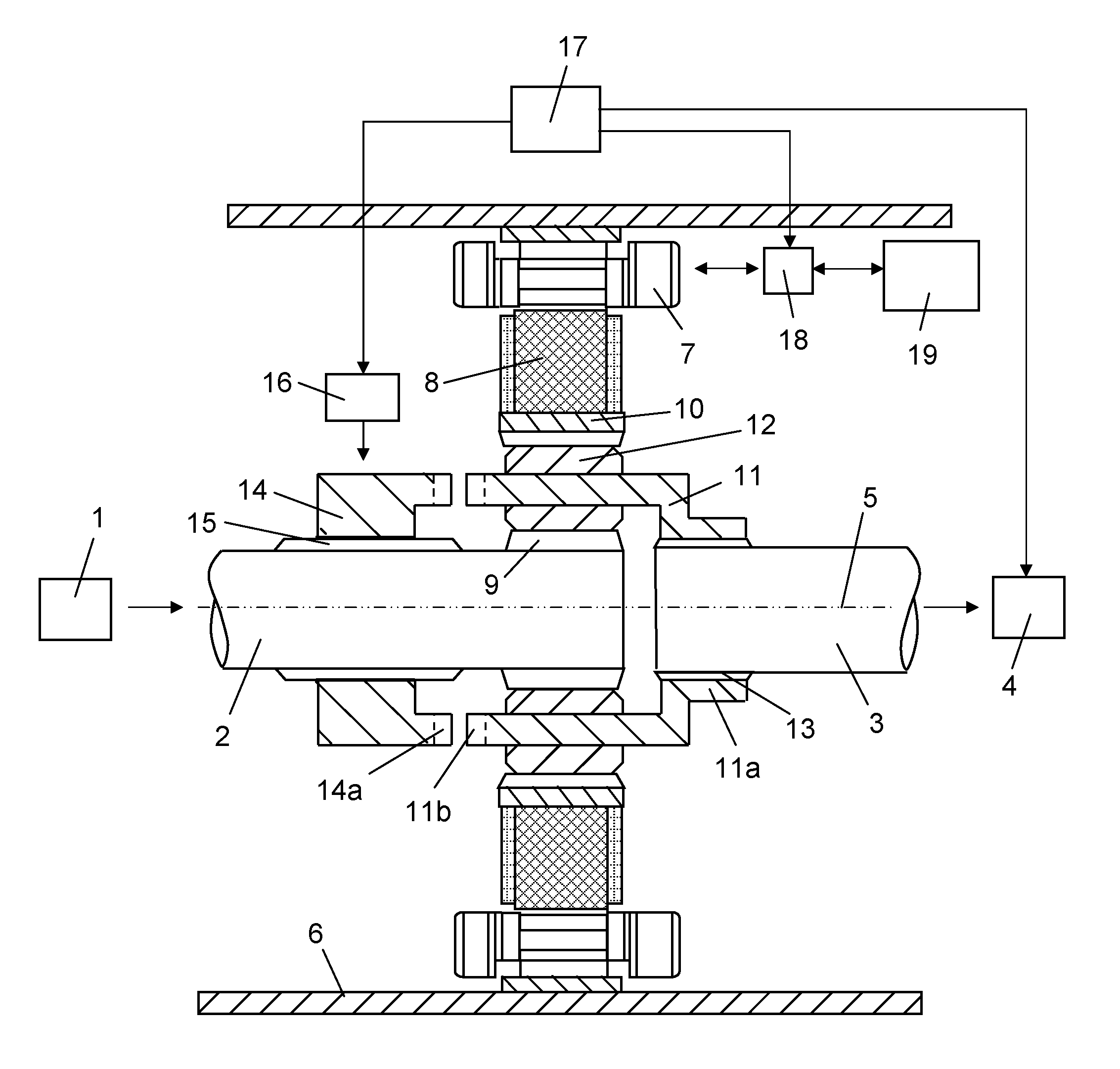
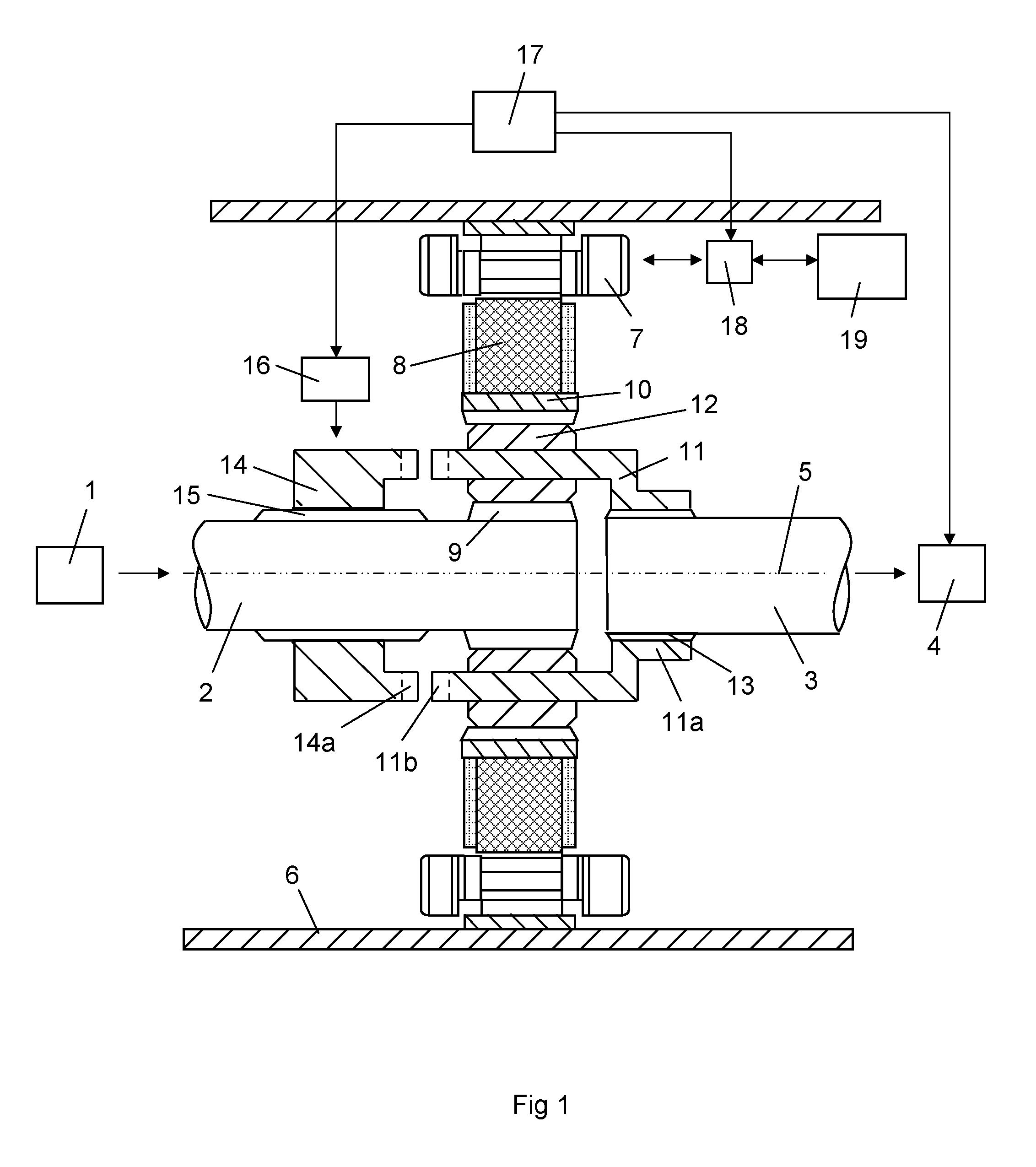
[0021]FIG. 1 depicts a propulsion system for operating a vehicle. The vehicle is in this case a hybrid vehicle powered primarily by a combustion engine 1 which may be a diesel engine 1. The engine 1 is provided with an output shaft 2. The engine output shaft 2 is arranged coaxially relative to an input shaft 3 to a gearbox 4. The engine output shaft 2 and the gearbox input shaft 3 are arranged for rotation about a common axis of rotation 5. The hybrid vehicle has a housing 6 which encloses an electrical machine and a planetary gear in a region which contains one end of the engine output shaft 2 and one end of the gearbox input shaft 3. The electrical machine comprises in a conventional way a stator 7 and a rotor 8. The stator 7 has a stator core fastened appropriately to the inside of the housing 6. The stator core comprises the stator's windings. The electrical machine is adapted in certain operating situations to using stored electrical energy to impart propulsive force to the gea...


PUM


Abstract

A propulsion system for a vehicle has output shaft (2) of a combustion engine (1), which is connected to a first component (9) of a planetary gear so that they rotate at a first speed (n1). An input shaft (3) of a gearbox (4) is connected to a second component (11) of the planetary gear so that they rotate at a second speed (n2). An electrical machine is connected to a third component (10) of the planetary gear so that the third component (10) rotates at a third speed (n3). A control unit (17) estimates in appropriate operating situations a desired speed (n2) for the gearbox input shaft (3). The unit receives information about the speed (n1) of the engine output shaft (2). It causes the electrical machine to give the third component (10) of the planetary gear a speed (n3) which in conjunction with the speed (n1) of the engine output shaft (2) results in the gearbox input shaft (3) assuming the desired speed (n2).

Description

BACKGROUND TO THE INVENTION AND PRIOR ART[0001]The present invention relates to a propulsion system for a vehicle according to the preamble of claim 1.[0002]Hybrid vehicles may be powered by a primary prime mover which may be a combustion engine, and by a secondary prime mover which may be an electrical machine. The electrical machine will be equipped with at least one battery to store electrical energy and with regulating equipment to regulate the flow of electrical energy between the battery and the electrical machine. The electrical machine may thus serve alternately as motor and generator, depending on the vehicle's operating state. When the vehicle is braked, the electrical machine generates electrical energy which is stored in the battery. The stored electrical energy is subsequently used to operate the vehicle. The electrical machine may be situated at a location between a clutch mechanism and the gearbox of the vehicle. For the sake of space, it is advantageous to connect th...

Claims


Application Information

Patent Timeline
Patent Type & Authority Applications(United States)
IPC IPC(8): F16H3/72B60L50/16
CPCF16H3/725B60K6/48B60K6/547B60W10/08B60W10/11B60W20/00B60W2710/1011B60Y2300/73Y02T10/62B60K6/40B60W10/10B60W20/10B60W30/19F16H61/0403F16H3/126F16H2306/40B60W20/30
Inventor ENGSTROM, JORGENBERGQUIST, MIKAEL
Owner SCANIA CV AB
Features
  • R&D
  • Intellectual Property
  • Life Sciences
  • Materials
  • Tech Scout
  • Unparalleled Data Quality
  • Higher Quality Content
  • 60% Fewer Hallucinations
Learn More