Biofilter

a biofilter and filter body technology, applied in the field of biofilters, can solve the problems of corrosive nature of gases or odorous air, surface treatment which is expensive and is corroding/wearing off quickly, and the effect of rapid corrosion to steel and concrete structures is easy to maintain and cost-effective construction

Inactive Publication Date: 2013-12-05
MALLINEN MATTI
View PDF2 Cites 8 Cited by
  • Summary
  • Abstract
  • Description
  • Claims
  • Application Information

AI Technical Summary

Benefits of technology

[0010]It is an object of the present invention to provide a solution which is a cost effective to build and easy to maintain. In the prior art solutions the corrosive nature of the gases or odorous air are taken care of by surface treatments which are expensive and are corroding / wearing off quickly. This means rapid corrosion to steel and concrete structures. With this invention the corrosive gases are not in contact with the steel structures. The filter media of the biofilter according to this invention is easy to change without interruptions to the purification process. It is easy and cost-effective to do by just changing the sack containing the filter media.
[0011]It is another object of this invention to provide a flexible solution which can be increased easily when needed. It has also collapsible structure (bolt connections in the filter body and foldable stowage space) which is easy to transport.
[0012]Another object of this invention is to provide a solution with a small used land area. This means smaller investments per used filter media area and better cost efficiency.

Problems solved by technology

In the prior art solutions the corrosive nature of the gases or odorous air are taken care of by surface treatments which are expensive and are corroding / wearing off quickly.
This means rapid corrosion to steel and concrete structures.

Method used


Image

  • Biofilter
  • Biofilter

Examples


Embodiment Construction

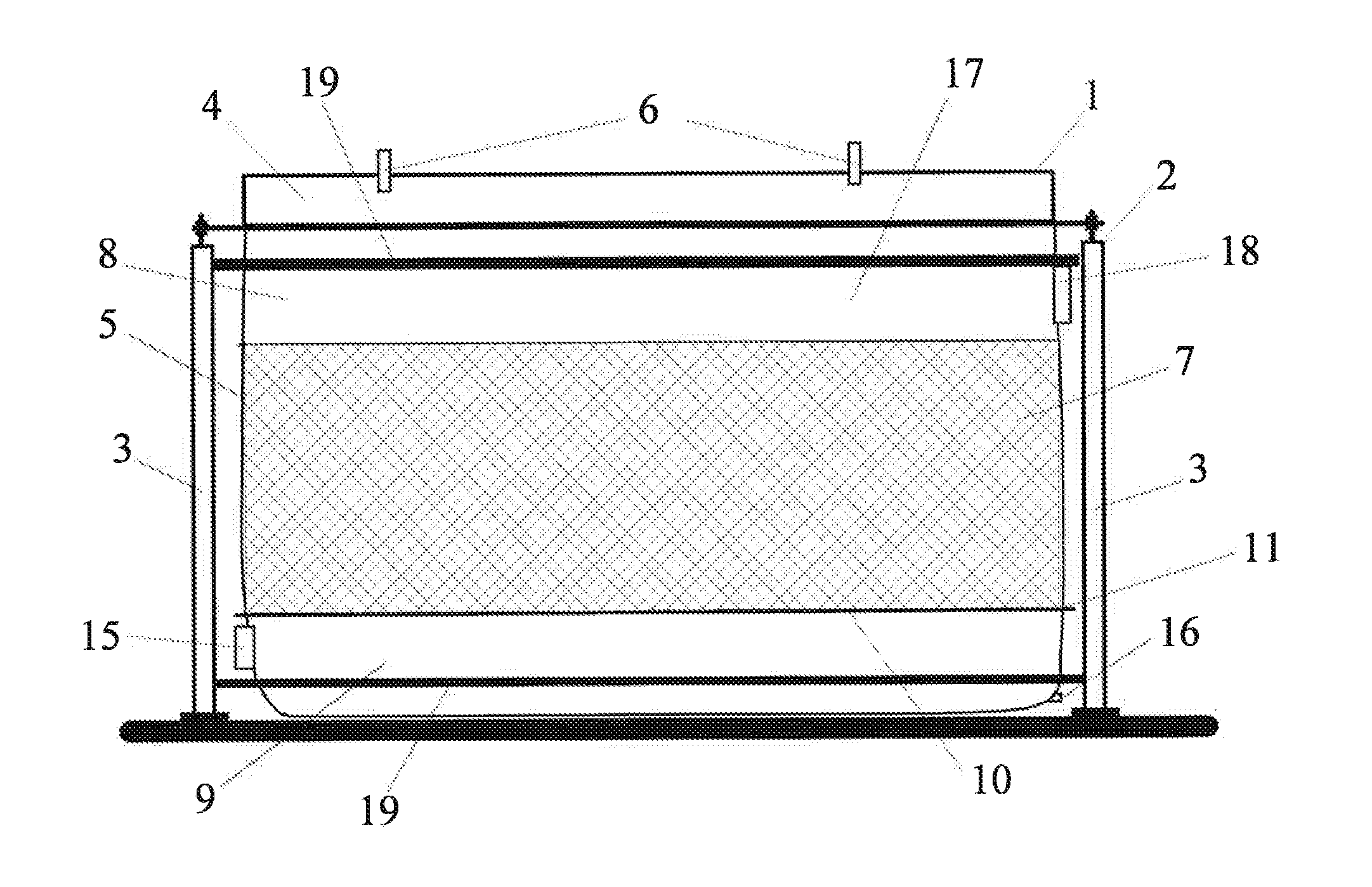
[0017]In FIG. 1 the biofilter 1 has a solid filter body 2 which includes several vertical supports 3. These vertical supports 3 are connected together with horizontal supports 19 to strengthen the structure. These horizontal and vertical supports are advantageously connected with bolt connections or such for easy dissemble. In another preferred embodiment the solid filter body 2 is designed so that the biofilters can be placed at top of another. These piles can include two or more biofilters. It is obvious that in this case the solid filter body 2 is much stronger than the body in FIG. 1 and has secured connections between piled biofilters.

[0018]The vertical supports 3 are connected directly to the rigid upper edge frame 4 of the stowage space 5. The rigid upper edge frame 4 has lifting shackles 6. With these lifting shackles 6 the stowage space 5 can be lifted apart from the solid filter body 2 for changing the filter media 7. The lifting operation can be arranged also using any pr...


PUM

PropertyMeasurementUnit
flexibleaaaaaaaaaa
timeaaaaaaaaaa
hardaaaaaaaaaa

Abstract

A biofilter (1) having filter media (7) in a stowage space (5) having sidewalls and a bottom, inlet opening (15) for the unpurified gases / air and the stowage space (5) is made of flexible gas-tight material filled at least partly with the filter media (7). A biofilter system having two or more biofilters (1) is also described.

Description

FIELD OF THE INVENTION[0001]This invention relates to a biofilterBACKGROUND OF THE INVENTION[0002]Biofilters are used to purificate odorous and VOC (volatile organic compound) gases and air. The technique is to run unpurified gases through the biomaterial which purifies the gases. Biofilters have been designed primarily for odour control at wastewater treatment plants, rendering plants, composting operations, chemical plants, paint industry, biogas fermentation plants, waste handling plants, livestock industry, food industry, beverage industry, etc. A common prior art technique is to build a building which has open airspace at the bottom of the building. On top of the airspace is metal grid or such, which holds the filter media / biomaterial on its place. The unpurified gases are led to the airspace and from there upwards through the filter media / biomaterial. On top of the filter media / biomaterial the purified gases are collected and led to the open air.[0003]There are also transporta...

Claims


Application Information

Patent Timeline
Patent Type & Authority Applications(United States)
IPC IPC(8): B01D46/00
CPCB01D46/0016B01D46/30B01D53/0415B01D53/44B01D53/85B01D2257/708B01D2257/90B01D2279/30Y02A50/20B01D53/34
Inventor MALLINEN, MATTI
Owner MALLINEN MATTI
Why Eureka
Try Eureka