Fuel Injection System for Diesel Engines with Compression Ignition

a technology of compression ignition and fuel injection system, which is applied in the direction of fuel injection apparatus, mechanical equipment, electric control, etc., can solve the problems of limited supplemental quantity of fuel, achieve the effects of reducing the temperature level, increasing the temperature and pressure in the combustion chamber, and reducing the nox components formed during the subsequent combustion

Inactive Publication Date: 2013-12-05
ABB TURBO SYST
View PDF12 Cites 4 Cited by
  • Summary
  • Abstract
  • Description
  • Claims
  • Application Information

AI Technical Summary

Benefits of technology

[0007]In further preferred embodiments of the invention, the injection angle of the supplemental injection nozzle is oriented so as to direct the injected supplemental quantity of diesel fuel into contact with one or more hot vaporizing surfaces within the combustion chamber, for example an exhaust valve, an area on the crown or top surface of the piston, or an area of the flame ring in the top area of the cylinder adjoining the cylinder head. The “injection angle” refers to the orientation of the central axis of the injection spray pattern, e.g. the central axis of the injection spray cone, or refers to the angular width of the spray pattern sufficient to impinge fuel onto the stated surfaces. Through the contact of the diesel fuel with such a hot vaporizing surface, this causes a reliable vaporization of the fuel and thus the formation of a homogenous mixture of the vaporized fuel with the air present in the combustion chamber. The supplemental quantity of fuel is limited, however, so that there is an extreme excess air quantity in the resulting homogenous mixture. Due to the prevailing extreme air excess as well as the relatively low temperature level in the combustion chamber at the time of the supplemental injection, this lean homogenous air / fuel mixture does not self-ignite. Thereby, the NOx components formed during the subsequent combustion can be reduced.
[0008]Furthermore, the non-ignitable homogenous air / fuel mixture present in the combustion chamber can reduce the temperature level in the combustion chamber. Particularly, the supplemental injected fuel serves to cool the particular “hot spot” within the combustion chamber at which the supplemental injected fuel is directed, e.g. the exhaust valve, the flame ring area, or the top surface of the piston. As further alternatives, the supplemental injected fuel may be directed at any combination of two or more of these areas, for example especially at the flame ring area and the exhaust valve, or at the flame ring area and the piston top surface, or at the exhaust valve and the piston top surface. This cooling can help to avoid the occurrence of detonation or diesel knock, for example.
[0009]Then, following the supplemental injection, the normal primary injection of fuel necessary for ignition and combustion is carried out, for example in a conventional manner. The primary injected fuel mixes into the homogenous lean air / fuel mixture already established in the combustion chamber by the supplemental injected fuel. The compression up-stroke of the piston has continued in the meantime between the supplemental fuel injection and the primary fuel injection, thereby increasing the temperature and the pressure in the combustion chamber, which then leads to the smooth homogenous ignition and combustion of the resultant air / fuel mixture including both the supplemental injected fuel and the primary injected fuel.

Problems solved by technology

The supplemental quantity of fuel is limited, however, so that there is an extreme excess air quantity in the resulting homogenous mixture.

Method used


Image

  • Fuel Injection System for Diesel Engines with Compression Ignition
  • Fuel Injection System for Diesel Engines with Compression Ignition
  • Fuel Injection System for Diesel Engines with Compression Ignition

Examples


Embodiment Construction

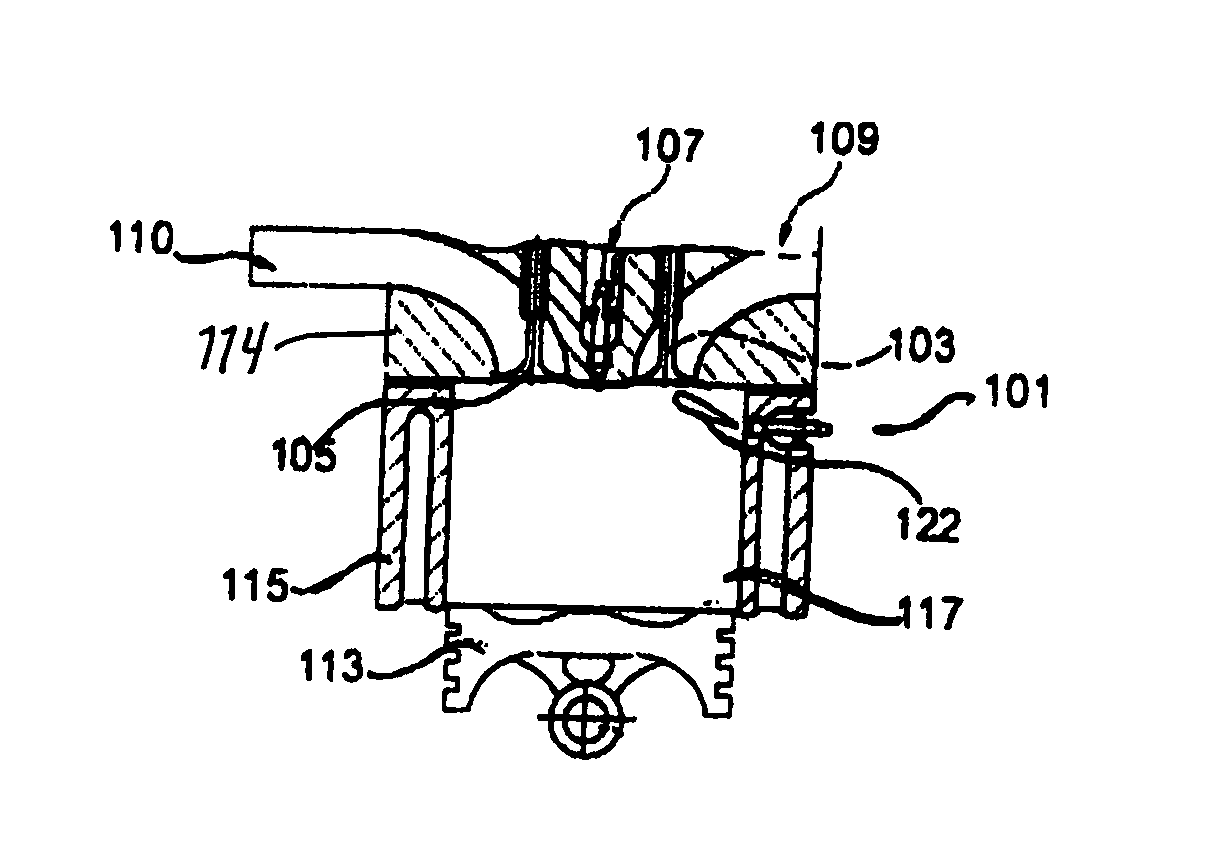
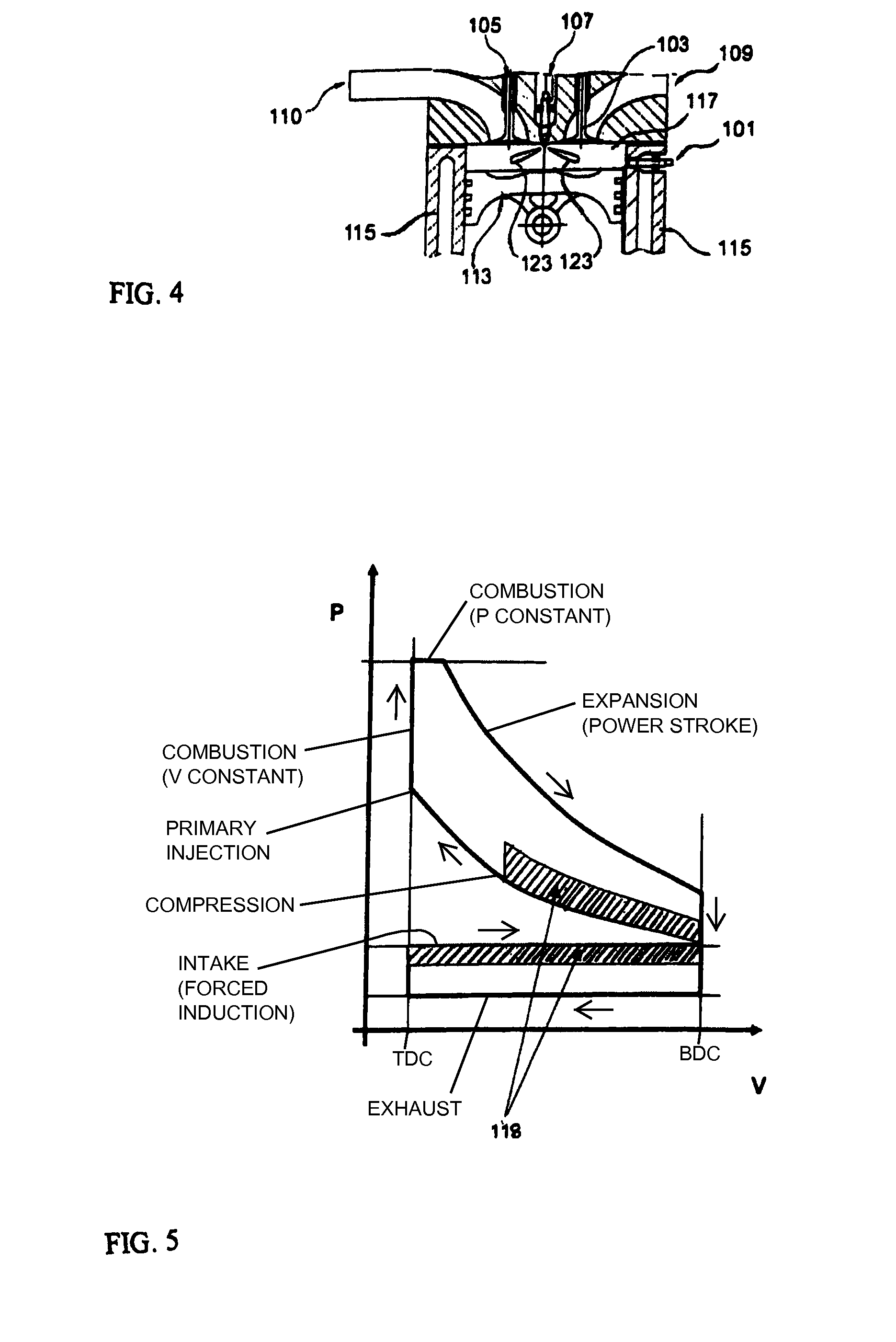
[0019]FIGS. 1 to 4 schematically represent a cross-section through a single cylinder of a diesel engine that has been equipped or modified according to the invention. Particularly, the arrangement includes a piston 113 movably arranged in a cylinder 115, and a cylinder head 114 connected to the open top of the cylinder 115 via a flame ring 119, or the flame ring is provided in the cylinder near the top end thereof adjacent to the head. Thus, a combustion chamber 117 is formed within the cylinder, namely bounded within the walls of the cylinder 115 between the movable piston 113 and the cylinder head 114. When referring to the “cylinder” herein, this term may include both the cylinder walls and the cylinder head.

[0020]An air inlet opening or passage 110 and an exhaust outlet opening or passage 109 are provided in the cylinder head 114. The inlet passage 110 and exhaust passage 109 are respectively equipped with a controlled inlet valve 105 and a controlled outlet valve 103, whereby t...


PUM


Abstract

In a fuel injection system and method for a diesel engine with compression induced ignition, NOx emissions are reduced by providing a supplemental fuel injection from a supplemental injection nozzle, in addition to the primary fuel injection through a primary injection nozzle. The supplemental injection nozzle injects a supplemental quantity of fuel onto a vaporization surface such as an exhaust valve, a flame ring area, or a top surface of the piston, in the combustion chamber, whereupon the supplemental fuel vaporizes and forms a lean air / fuel mixture. Thereafter, the primary injection nozzle injects the main fuel charge into the combustion chamber, to produce a rich air / fuel combustion mixture, which is then ignited and combusts.

Description

PRIORITY CLAIM[0001]This application is based on and claims the priority under 35 USC 119 of German Patent Application 10 2012 011 149.5, filed on Jun. 5, 2012, the entire disclosure of which is incorporated herein by reference.FIELD OF THE INVENTION[0002]The invention relates to a fuel injection system and method for diesel engines using compression ignition, wherein fuel injection nozzles carry out a controlled injection of fuel into a combustion chamber formed by a piston in a cylinder with controllable inlet and exhaust valves.BACKGROUND INFORMATION[0003]In a conventional diesel engine, diesel fuel is injected into the combustion chamber in the cylinder, for example from a fuel injection nozzle located approximately centrally above the combustion chamber in the head of the engine. As the air charge in the cylinder is compressed during the compression up-stroke of the piston, the compression causes the air to be heated to a high temperature, which is sufficiently high to cause sp...

Claims


Application Information

Patent Timeline
Patent Type & Authority Applications(United States)
IPC IPC(8): F02D41/40
CPCF02D41/402F02D41/3047F02D41/3094Y02T10/12Y02T10/40F02D41/30F02M47/00F02M63/00
Inventor MATHEY, CHRISTOPHTREMULI, PAOLO
Owner ABB TURBO SYST
Why Eureka
Try Eureka