Hydraulic brake device

a brake device and hydraulic technology, applied in the direction of fluid actuated brakes, braking elements, brake types, etc., can solve the problems of fluid leakage, brake system malfunction, abrasion and wear, etc., to reduce operation resistance, improve fluid leakage, and reduce deformational stress

Inactive Publication Date: 2013-12-05
FRILIGENTS
View PDF11 Cites 9 Cited by
  • Summary
  • Abstract
  • Description
  • Claims
  • Application Information

AI Technical Summary

Benefits of technology

[0010]With the above arrangement, the present invention fastens the sealing bolt to the caliper body to form a sealed pressure chamber, in order to prevent fluid leakage and to compress the elastic enclosure member for driving the brake pad mounting assembly to achieve the function of braking. The elastic enclosure member is of a corrugated configuration to reduce deformational stress of the enclosure member of low elasticity material so as to reduce operation resistance and improve fluid leakage. Further, the caliper body is formed with a plurality of vent openings for guiding cold fresh air into the caliper body to achieve heat dissipation purposes.

Problems solved by technology

In such a known driving structure of pistons 20, the pistons 20 are constantly set in sliding movement with seal rings 23 and this leads to abrasion and wear.
Particularly, the pistons 20 have cylindrical circumferences that carry fluid and such fluid may get out of the pressure chamber through repeated operation, thereby causing fluid leakage.
The leakage of fluid of a brake system will lead to malfunctioning of the brake system and this is an intolerable issue of braking.
Rubbers or other materials made through chemical measures suffer common problems of fluid absorption and aging.
The manufacture cost will be surely high.
This is also a drawback.
Particularly, a fixing plate used in the conventional device must be fixed by bolts and the gap around threading is a way of leakage.
The operation is thus not good enough for users and further improvement must be made.

Method used


Image

  • Hydraulic brake device
  • Hydraulic brake device
  • Hydraulic brake device

Examples


Embodiment Construction

[0022]The following descriptions are exemplary embodiments only, and are not intended to limit the scope, applicability or configuration of the invention in any way. Rather, the following description provides a convenient illustration for implementing exemplary embodiments of the invention. Various changes to the described embodiments may be made in the function and arrangement of the elements described without departing from the scope of the invention as set forth in the appended claims.

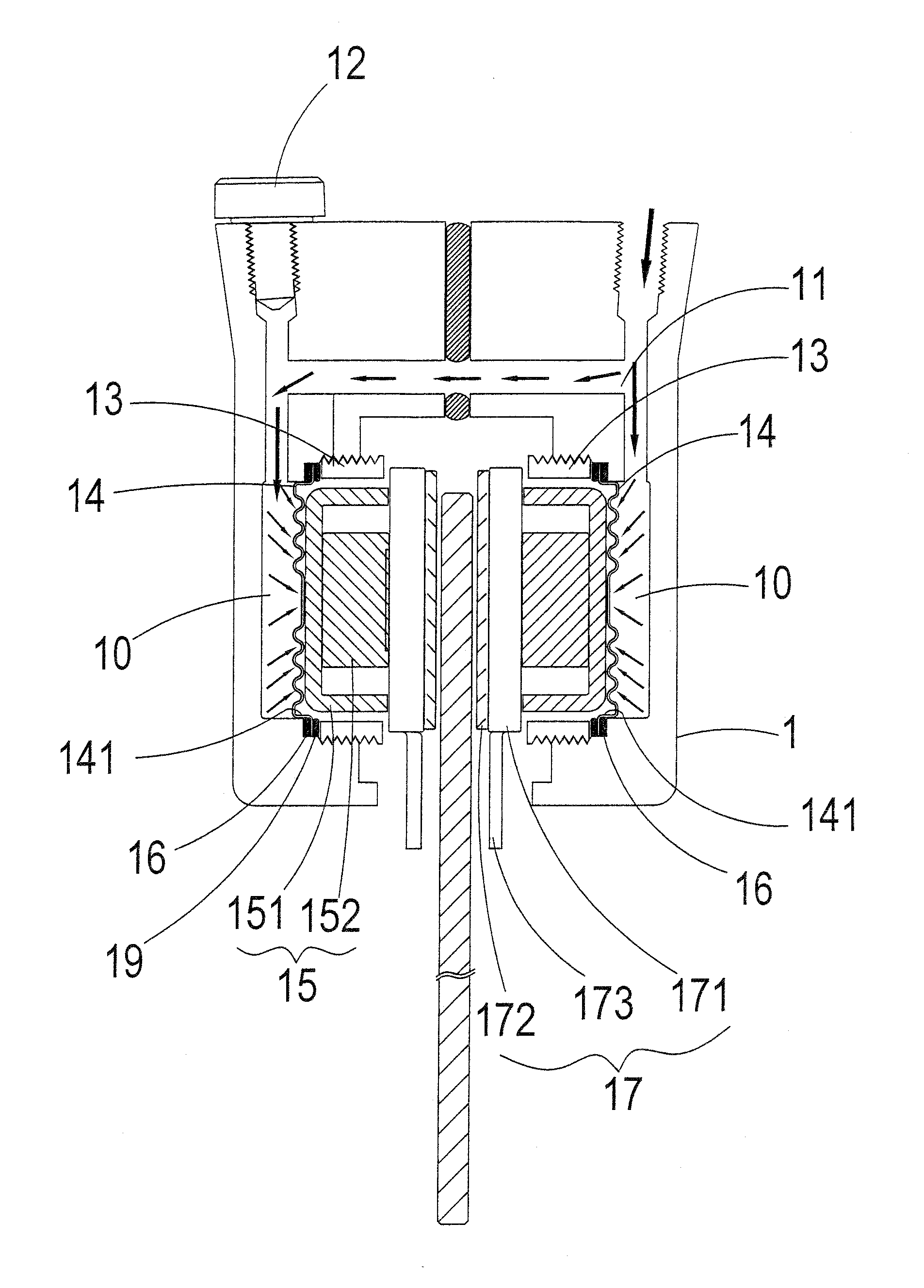
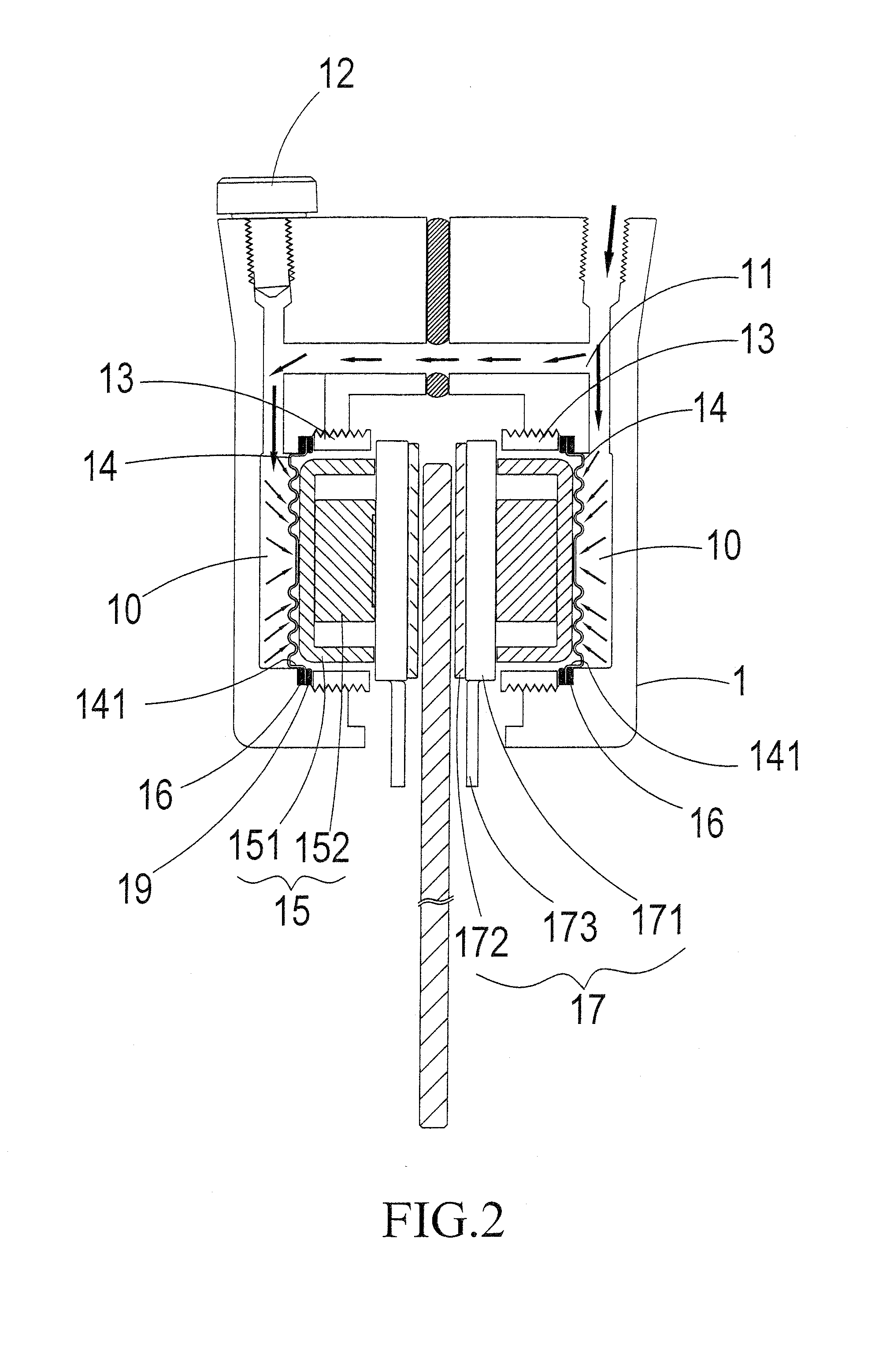
[0023]Referring to FIG. 2, which is a cross-sectional view showing a preferred embodiment of the present invention, the drawing clearly shows that the present invention provides a hydraulic brake device, which comprises the following constituent components:

[0024]At least one caliper body 1 defines therein a pressure chamber 10. The caliper body 1 also defines therein fluid passages 11 communicating with the pressure chamber 10. The caliper body 1 comprises at least one sealing bolt 12 mounted theret...


PUM


Abstract

A hydraulic brake device includes at least one caliper body that defines a pressure chamber, at least one elastic enclosure member that is arranged inside the caliper body to operate in combination with the pressure chamber and shows a corrugated configuration, and at least one brake pad mounting assembly, which is arranged on the elastic enclosure member at the side away from the pressure chamber. With fluid passages provided in communication with the pressure chamber, hydraulic fluid can be supplied to compress the elastic enclosure member for driving the brake pad mounting assembly and the brake lining assembly to effect braking. The corrugated configuration helps reducing deformational stress induced in the elastic enclosure member and also reducing operation resistance. A ventilation section is also provided on the caliper body to draw in fresh air for heat dissipating purposes.

Description

TECHNICAL FIELD OF THE INVENTION[0001]The present invention generally relates to a hydraulic brake device, and more particularly to a hydraulic brake device that uses combined operation of fluid passages, a pressure chamber, and an elastic enclosure member to compress the elastic enclosure member for driving a brake pad mounting assembly to achieve the purposes of braking and improving fluid leakage and also to improve heat dissipation through a ventilation section provided on a caliper body.DESCRIPTION OF THE PRIOR ART[0002]FIG. 1 is a schematic view showing a conventional hydraulic brake device, which uses hydraulic fluid to drive pistons 20 and brake pads 21 to tightly clamp a brake disk 22 in order to effect braking. In such a known driving structure of pistons 20, the pistons 20 are constantly set in sliding movement with seal rings 23 and this leads to abrasion and wear. Particularly, the pistons 20 have cylindrical circumferences that carry fluid and such fluid may get out of...

Claims


Application Information

Patent Timeline
Patent Type & Authority Applications(United States)
IPC IPC(8): F16D65/22F16D65/847F16D55/226
CPCF16D65/847F16D65/183F16D55/228
Inventor HUANG, YU-SUNG
Owner FRILIGENTS
Why Eureka
Try Eureka