Impeller, centrifugal pump including the same, and aircraft fuel system including the centrifugal pump

a technology of centrifugal pump and impeller, which is applied in the direction of liquid fuel engines, machines/engines, stators, etc., can solve the problems of insufficient pressure, inefficient pressurization of fuel, and inability to achieve insufficient pressure, so as to facilitate fluid flow

Inactive Publication Date: 2013-12-05
HONEYWELL INT INC
View PDF8 Cites 11 Cited by
  • Summary
  • Abstract
  • Description
  • Claims
  • Application Information

AI Technical Summary

Benefits of technology

[0009]In another embodiment, an aircraft fuel system includes a fuel tank, a centrifugal pump, and a main fuel line. The centrifugal pump is in fluid communication with the fuel tank for receiving fuel from the fuel tank. The main fuel line in fluid communication with the centrifugal pump for receiving pressurized fuel from the centrifugal pump. The centrifugal pump includes a pump housing including a fluid inlet and a fluid outlet. An impeller is disposed in the housing and is rotatable about a rotational axis. The impeller includes a central hub that is disposed along a rotational axis of the impeller and that defines an axial bore that extends through at least a portion of the central hub along the rotational axis. The central hub furthe...

Problems solved by technology

At the low fuel inlet pressures, a high amount of vaporized fuel may be present with liquid fuel at the fuel inlet and may result in inefficient pressurization of the fuel.
As a result, insufficient pressures may be realized in the pressurized fuel based upon the high amount of vaporized fuel at the fuel inlet, or pressurization may ...

Method used


Image

  • Impeller, centrifugal pump including the same, and aircraft fuel system including the centrifugal pump
  • Impeller, centrifugal pump including the same, and aircraft fuel system including the centrifugal pump
  • Impeller, centrifugal pump including the same, and aircraft fuel system including the centrifugal pump

Examples


Embodiment Construction

[0014]The following detailed description is merely exemplary in nature and is not intended to limit the invention or the application and uses of the invention. Furthermore, there is no intention to be bound by any theory presented in the preceding background or the following detailed description.

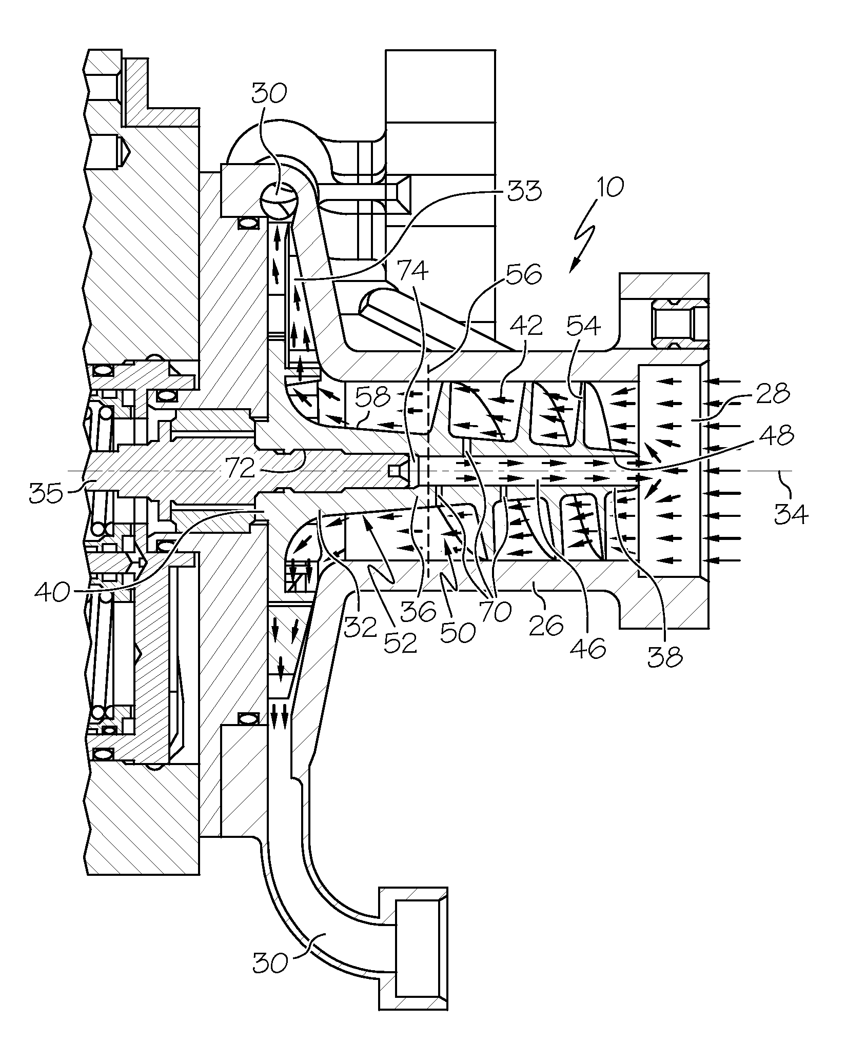
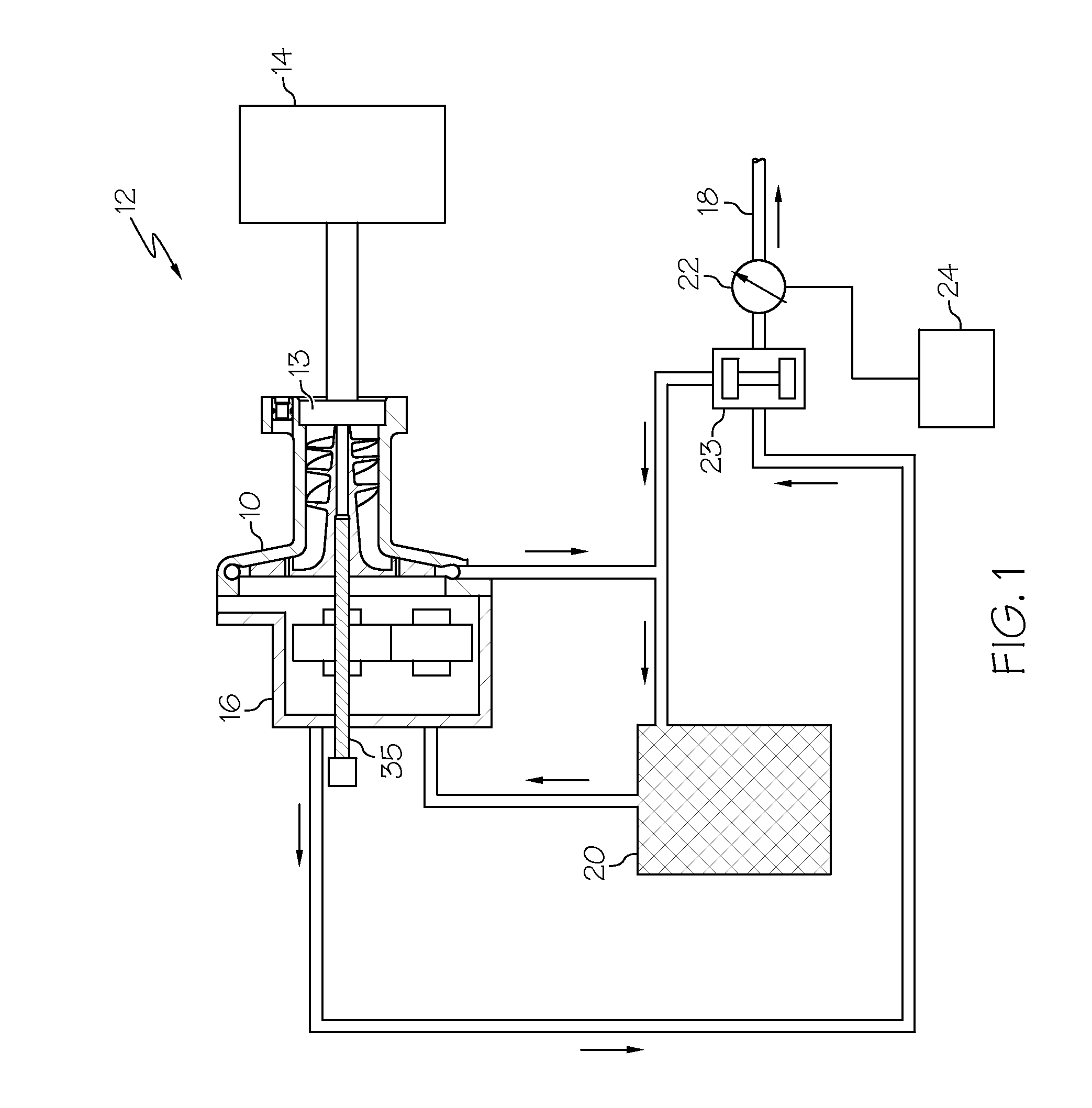
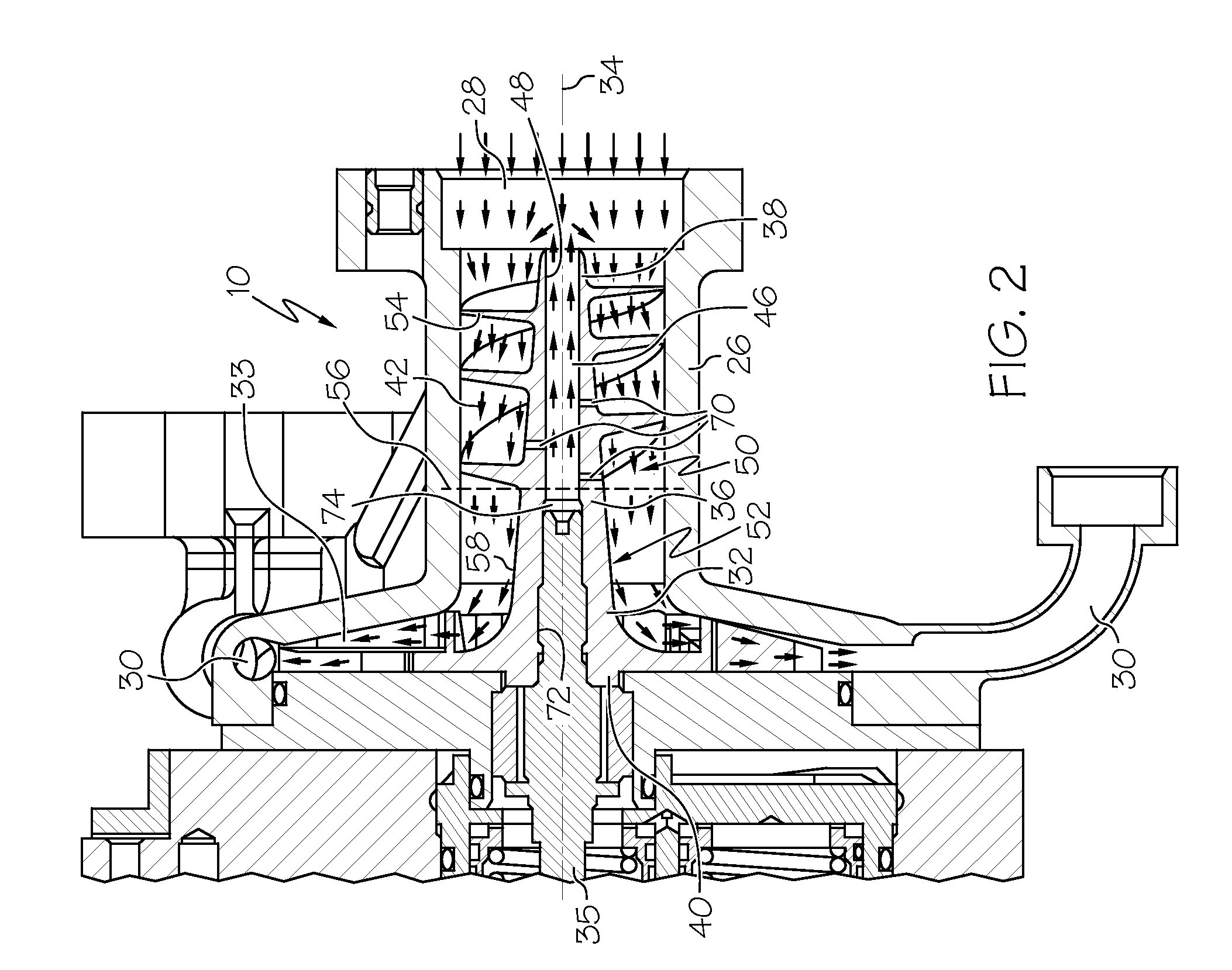
[0015]An impeller, a centrifugal pump including the impeller, and an aircraft fuel system including the centrifugal pump are provided herein. The impeller maximizes centrifugal pump efficiency, particularly when a fluid input having a high vaporized fluid content, by separating at least some vaporized fluid that travels through the impeller in an inducer section of the impeller and by returning the vaporized fluid upstream through a central hub of the impeller. By separating at least some of the vaporized fluid and returning the vaporized fluid upstream, a higher proportion of liquid is ultimately present in the fluid that is pressurized by the impeller. Because higher liquid to vapor conten...


PUM


Abstract

An impeller, a centrifugal pump, and an aircraft fuel system are provided. The impeller includes a central hub disposed along a rotational axis of the impeller and that defines an axial bore extending through at least a portion of the central hub along the rotational axis. The central hub further defines an opening to the axial bore at a leading end of the central hub. The impeller further includes an impeller section spaced from the leading end and that includes at least one impeller vane fixed to the central hub. The impeller further includes an inducer section that is disposed between the leading end of the central hub and the impeller section and that includes at least one inducer vane extending along an outer surface of the central hub. The central hub defines at least one radial aperture in the inducer section in fluid communication with the axial bore.

Description

TECHNICAL FIELD[0001]The present invention generally relates to an impeller for a centrifugal pump, a centrifugal pump including the impeller, and an aircraft fuel system including the centrifugal pump. In particular, the present invention relates to an impeller that maximizes centrifugal pump efficiency, particularly in the presence of fluid input having a vaporized fluid and liquid fluid, a centrifugal pump including the impeller, and an aircraft fuel system including the centrifugal pump.BACKGROUND[0002]Typical gas turbine engine fuel supply systems include a fuel source, such as a fuel tank, and one or more pumps that draw fuel from the fuel tank and deliver pressurized fuel to the fuel manifolds and fuel nozzles in the engine combustor via a main supply line. These pumps may include an aircraft or tank level pump, a boost pump, and a high pressure pump. The boost pump is typically a centrifugal pump and the high pressure pump is typically a gear pump, though in some application...

Claims


Application Information

Patent Timeline
IPC IPC(8): B64D37/02F04D1/04
CPCF04D1/025F04D29/2277F04D29/2288
Inventor LEWIS, STEVEN ALAN
Owner HONEYWELL INT INC
Why Eureka
Try Eureka