Ophthalmologic apparatus

a technology of ophthalmologic equipment and ophthalmologic tubes, which is applied in the field of ophthalmologic devices, can solve the problems of reducing image quality and longer inspection time, and achieve the effects of preventing image quality from being deteriorated, ensuring safety, and preventing inspection time from becoming longer

Inactive Publication Date: 2013-12-05
CANON KK
View PDF2 Cites 11 Cited by
  • Summary
  • Abstract
  • Description
  • Claims
  • Application Information

AI Technical Summary

Benefits of technology

[0007]The present invention is directed to an ophthalmologic apparatus capable of preventing image qua

Problems solved by technology

However, when turning ON/OFF of the light source is controlled, it takes longer time from turning-ON of the light source to stabilization of the emitted beam, and as a result, it causes a problem of longer inspection time.
In other words, as compared with a case where the subject'

Method used


Image

  • Ophthalmologic apparatus
  • Ophthalmologic apparatus
  • Ophthalmologic apparatus

Examples


Embodiment Construction

[0022]Various exemplary embodiments, features, and aspects of the invention will be described in detail below with reference to the drawings. The present invention is not limited to the exemplary embodiments described below. Various changes and modifications can be made within the scope of the present invention.

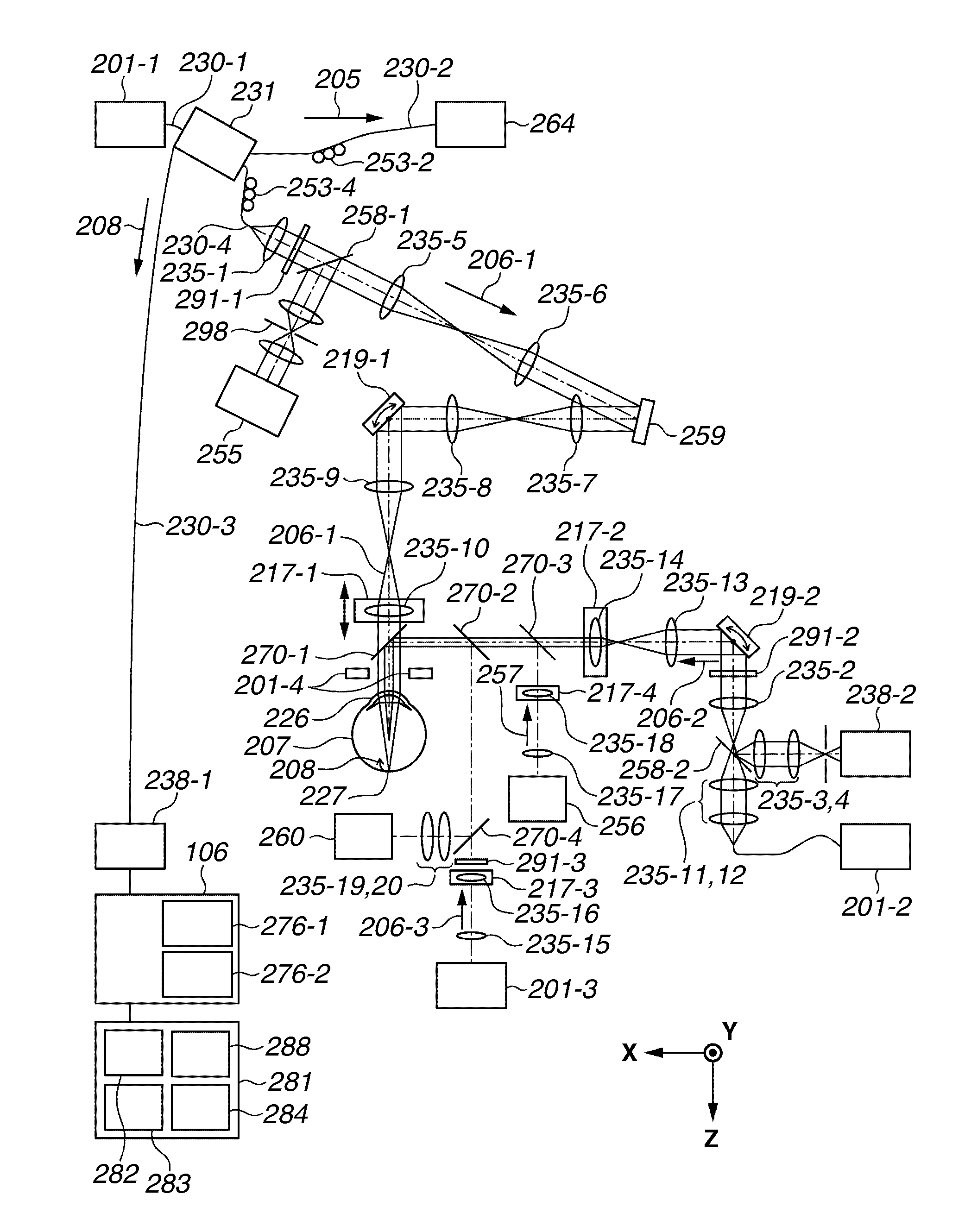
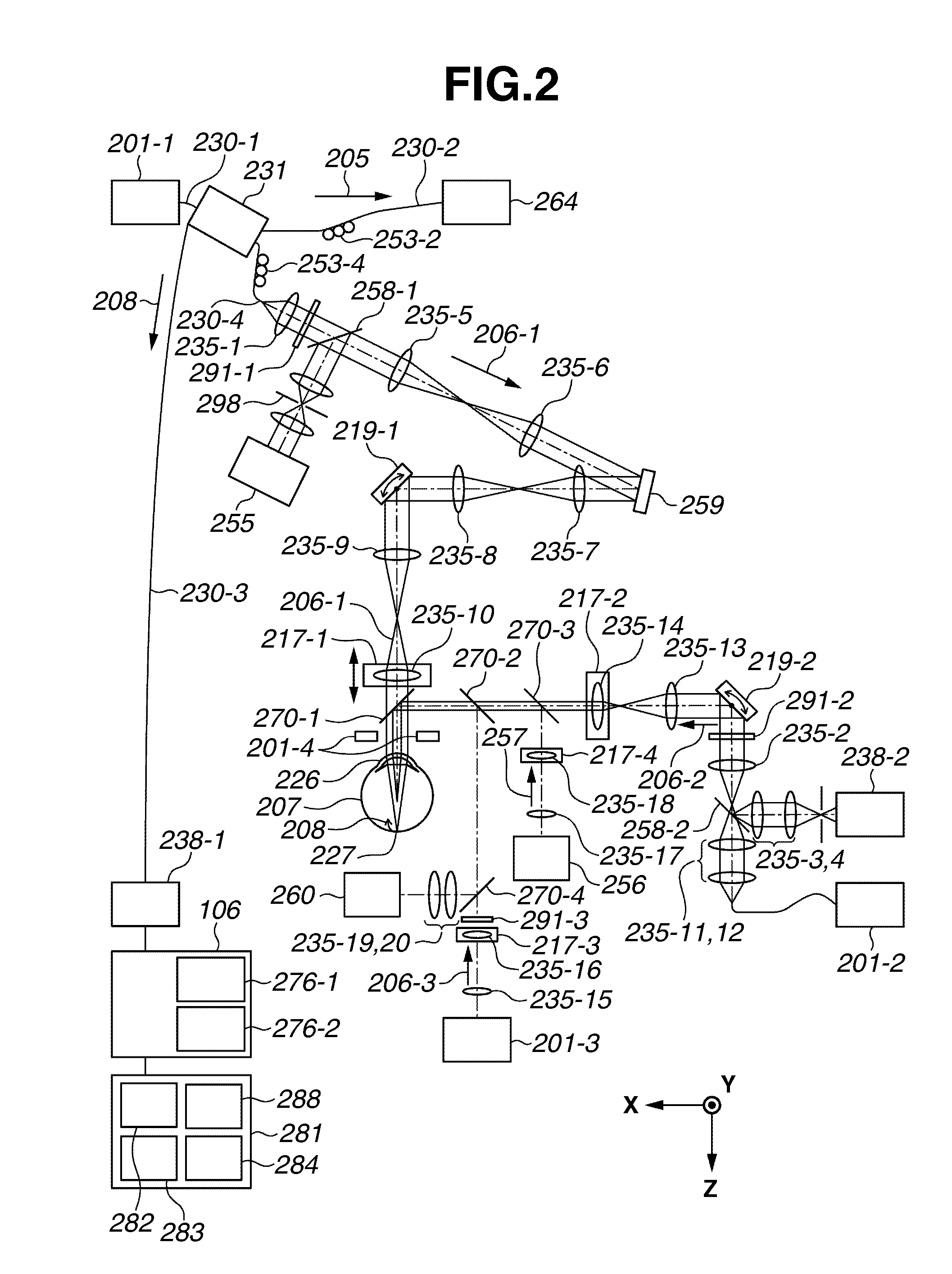
[0023]In an exemplary embodiment, as an ophthalmologic apparatus, an AOSLO apparatus according to the present invention will be described. The AOSLO apparatus, which includes an adaptive optical system, captures a high lateral resolution planar image (hereinafter, may be referred to as an AOSLO image) of a fundus of a subject's eye.

[0024]For the purpose of assisting obtaining of the AOSLO image, the AOSLO apparatus includes a WFSLO unit for capturing a wide field angle planar image (WFSLO image). The AOSLO apparatus further includes an anterior eye portion observation unit for grasping the incident position of a measuring beam, and a fixation lamp unit for guiding a line of s...


PUM


Abstract

An ophthalmologic apparatus includes an aberration measurement unit configured to measure aberration caused by a subject's eye by using a return beam of a first measuring beam from the subject's eye, a correction unit configured to correct aberration of a return beam of a second measuring beam from the subject's eye caused by the subject's eye based on the aberration measured by the aberration measurement unit, a first acquisition unit configured to obtain a first image of the subject's eye by using the aberration-corrected return beam of the second measuring beam from the subject's eye, and a control unit configured to enter one of the first measuring beam and the second measuring beam into the subject's eye while limiting entry of the other measuring beams into the subject's eye.

Description

BACKGROUND OF THE INVENTION[0001]1. Field of the Invention[0002]The present invention relates to an ophthalmologic apparatus.[0003]2. Description of the Related Art[0004]A scanning laser ophthalmoscope (SLO), which is an ophthalmologic apparatus using a principle of a confocal laser microscope, performs raster scanning for, for example, a fundus of a subject's eye with a laser that is a measuring beam, and obtains a planar image based on the intensity of its return beam from the subject's eye with high resolution at a high speed. Hereinafter, an apparatus that captures such a planar image may be referred to as a SLO apparatus.[0005]There is known a technology for measuring aberration caused by the subject's eye by a wavefront sensor in real time, and correcting the aberration caused by the subject's eye by a wavefront correction device. Japanese Patent Application Laid-Open No. 2010-259543 discusses an adaptive optics SLO (hereinafter, may be referred to as AOSLO apparatus) having a...

Claims


Application Information

Patent Timeline
IPC IPC(8): A61B3/10
CPCA61B3/1025
Inventor MOROHASHI, KAZUYA
Owner CANON KK
Why Eureka
Try Eureka