Fiber network events measurement apparatus

Active Publication Date: 2013-12-05
ASCENTAC INC
View PDF4 Cites 4 Cited by
  • Summary
  • Abstract
  • Description
  • Claims
  • Application Information

AI Technical Summary

Benefits of technology

[0023]With respect to the measurement apparatus of the invention, the compound trace result provides information including the signal attenuation and the event positions of the fiber network routes. The measurement appara

Problems solved by technology

However, the signals attenuate when they are transmitting in fiber cables.
The information d

Method used


Image

  • Fiber network events measurement apparatus
  • Fiber network events measurement apparatus
  • Fiber network events measurement apparatus

Examples


Example

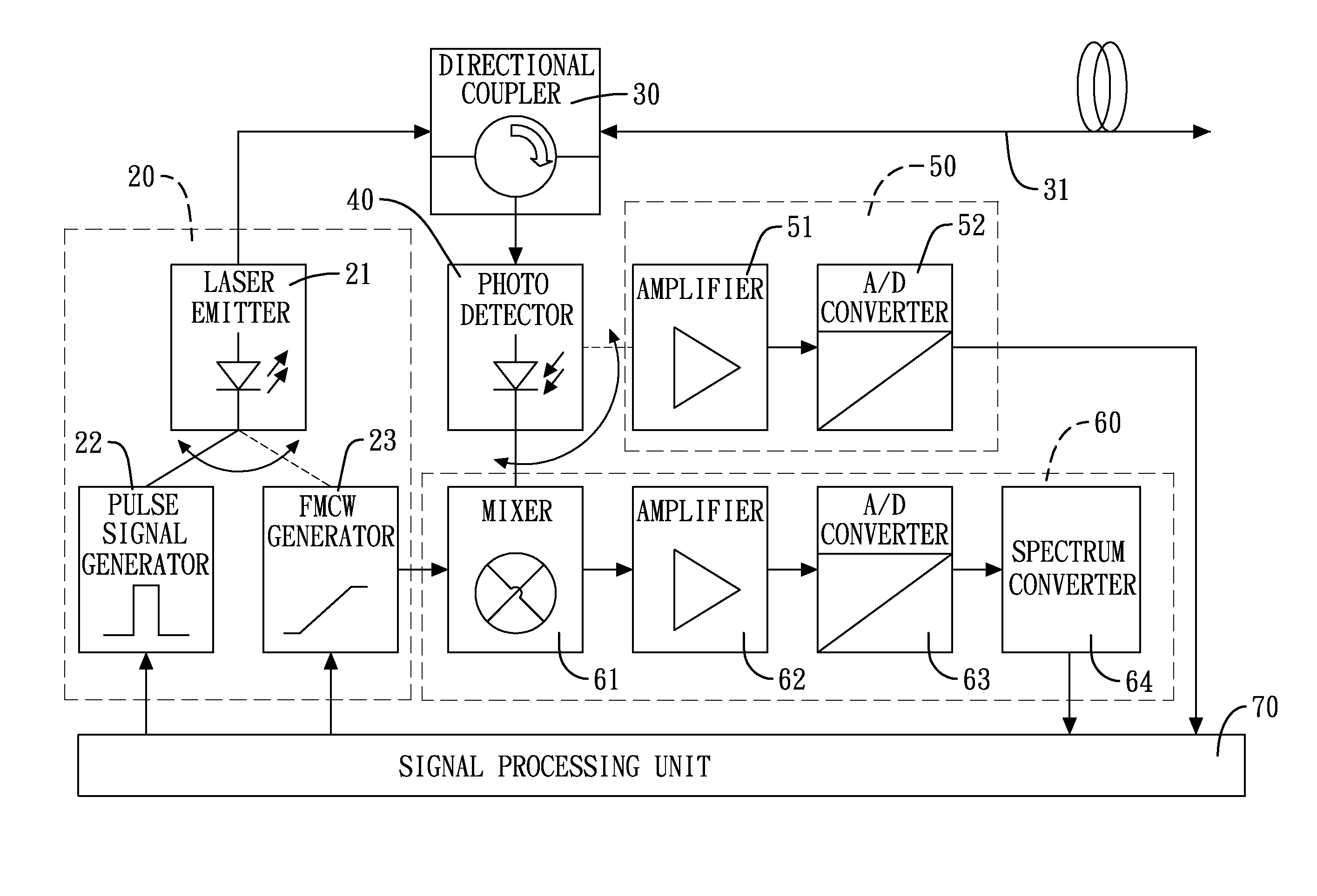
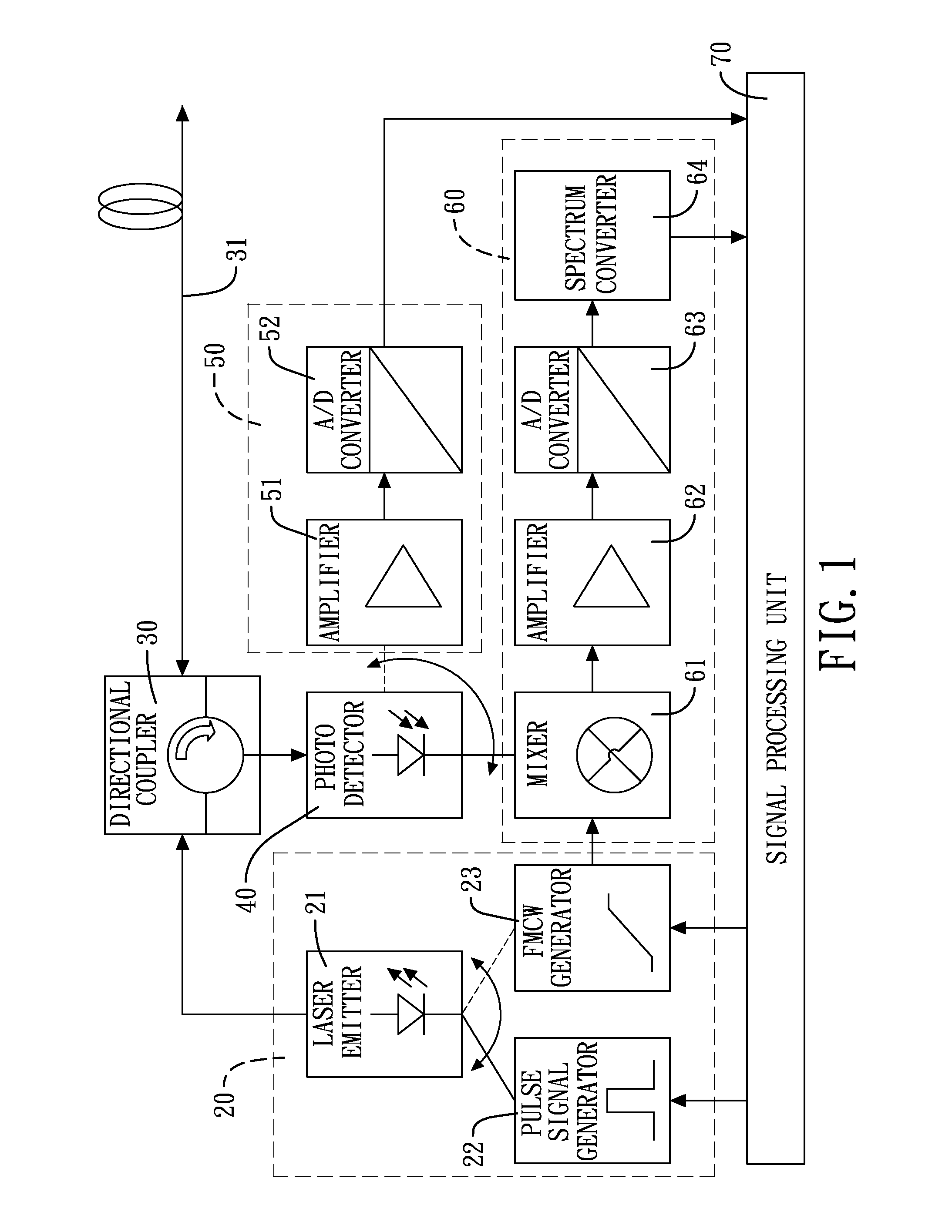
[0032]With reference to FIG. 1, a first embodiment of the measurement apparatus of the invention is disclosed. The measurement apparatus comprises a laser module 20, a directional coupler 30, a photo detector 40, a pulse signal converting module 50, an FMCW module 60 and a signal control unit 70.

[0033]The laser module 20 comprises a laser emitter 21, a pulse signal generator 22 and an FMCW generator 23. The laser emitter 21 is adapted to emit a testing beam along a transmitting route. The pulse signal generator 22 is adapted to generate a periodic pulse signal. The pulse signal can be combined with the testing beam by a modulator to become a pulse signal detecting beam as a first measurement beam. The FMCW generator 23 is adapted to generate an FMCW signal, wherein the FMCW signal is periodic and linear. The FMCW signal can be combined with the testing beam by a modulator to become a FMCW detecting beam as a second measurement beam.

[0034]The directional coupler 30 is mounted in the ...


PUM


Abstract

A fiber network events measurement apparatus has a laser module alternately generating a pulse signal detecting beam and an FMCW detecting beam. The beams are sent to the fiber network route through a directional coupler. A photo detector receives feedback energy of the beams transmitting in the fiber network route and converts the feedback energy into electronic signals. A mixer uses a frequency difference calculation to obtain a comparison result according to an original and a reflected FMCW signal. The electronic signal is converted into a digital signal by an A/D converter. A signal control unit then obtains a compound trace result including information of characteristic trace and event positions. The compound trace result shows a fiber characteristic trace and event position trace for measuring the fiber network routes.

Description

CROSS-REFERENCE TO RELATED APPLICATIONS[0001]This application claims the benefit of Taiwan patent application No. 101210189, filed on May 29, 2012, the disclosure of which is incorporated herein in its entirety by reference.BACKGROUND OF THE INVENTION[0002]1. Field of the Invention[0003]The present invention relates to a measurement apparatus, and more particularly to a fiber network events measurement apparatus.[0004]2. Description of Related Art[0005]With reference to FIG. 6, a conventional fiber network testing device, i.e. an FMCW (Frequency-modulated continuous-wave) device comprises a laser emitter 80, an FMCW generator 81, a directional coupler 82, a photo detector 83, a signal converter 84 and a signal control unit 85.[0006]The laser emitter 80 emits a testing beam. The FMCW generator 81 generates a periodic FMCW signal. The testing beam and the FMCW signal are combined and are outputted to a fiber network route 86 through the directional coupler 82. When the FMCW signal is ...

Claims


Application Information

Patent Timeline
IPC IPC(8): H04B10/07
CPCH04B10/07H04B10/071
Inventor HSIAO, CHING-WENWU, HSUAN-HUNGLIN, SHIH-TIENHUNG, FU-CHUNCHEN, YU-SHUWU, CHING-LINSU, CHUN-HUNG
Owner ASCENTAC INC
Why Eureka
Try Eureka