Eureka AIR delivers breakthrough ideas for toughest innovation challenges, trusted by R&D personnel around the world.

Anti-surge speed control

a speed control and speed control technology, applied in the direction of pump control, non-positive displacement fluid engine, climate sustainability, etc., can solve the problem of compressor moving off the peak efficiency operating line and into a surge condition, serious damage to the compressor impeller, drive mechanism and components, and surge can occur quite unaşteptably

Inactive Publication Date: 2013-12-05
PRAXAIR TECH INC
View PDF0 Cites 20 Cited by
  • Summary
  • Abstract
  • Description
  • Claims
  • Application Information

AI Technical Summary

Benefits of technology

The present invention provides a method for controlling the speed of a centrifugal compressor in a vacuum pressure swing adsorption apparatus. The method involves measuring a parameter related to the flow rate of gas entering the compressor and calculating the optimal speed based on the pressure ratio of the outlet to inlet pressure. A feed back multiplier is determined and used to control the compressor speed. The speed control is done to prevent surge conditions and improve efficiency. The control system also includes a total speed multiplier that is set based on the feed back multiplier and the pressure ratio. The control system can adjust the speed by manipulating the feed back multiplier and the total speed multiplier during different stages of the repeating cycle.

Problems solved by technology

There are, however, situations that can cause the compressor to move off the peak efficiency operating line and into a surge condition.
This alternating flow pattern has been found to be an unstable condition that can result in serious damage to the compressor impeller, drive mechanism and components.
Additionally, during the evacuation and purge steps and particularly during the transition between the purge and evacuation steps, surge can occur quite unexpectantly.

Method used


Image

  • Anti-surge speed control
  • Anti-surge speed control
  • Anti-surge speed control

Examples


Embodiment Construction

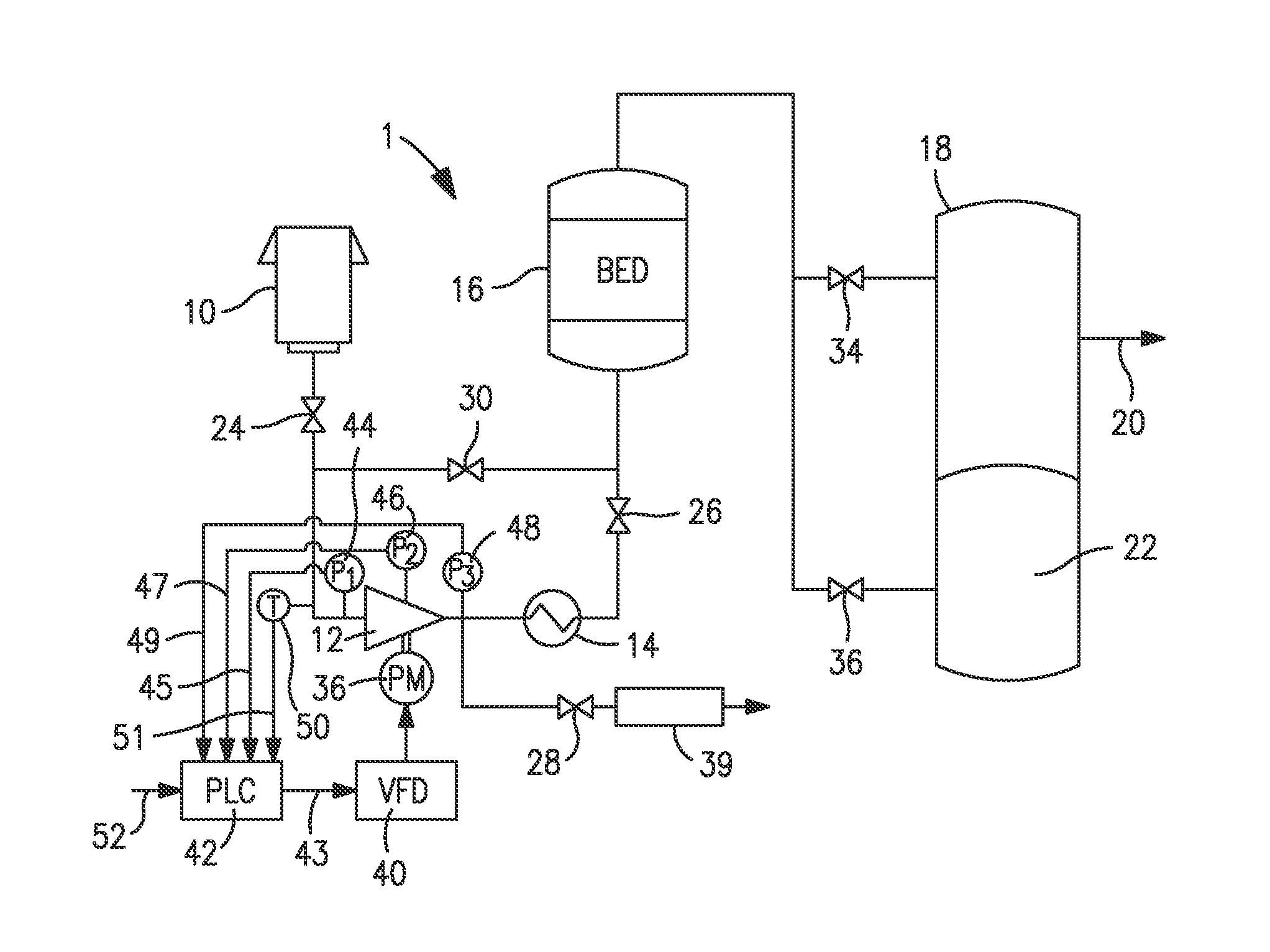
[0027]With reference to FIG. 1, a vacuum pressure swing adsorption apparatus 1 is illustrated that is designed to produce an oxygen product. Although vacuum pressure swing adsorption apparatus 1 is a single bed design, it is understood that this is for purposes of illustration and the present invention would have equal applicability to a multiple bed design using a single or multiple compressors designed to pressurize and evacuate an adsorbent bed or beds. Furthermore, the present invention is equally applicable to vacuum pressure swing adsorption apparatus designed to produce other products such as carbon dioxide, nitrogen, hydrogen or helium. As such, the vacuum pressure swing adsorption apparatus 1 is shown and described herein for exemplary purposes only.

[0028]Vacuum pressure swing adsorption apparatus 1 draws air through an inlet 10 that contains a filter to filter out particulates. The resulting air feed stream is drawn by a compressor 12 having an after cooler 14 to remove th...


PUM


Abstract

The present invention relates to a method and control system to control the speed of a centrifugal compressor operating within a vacuum pressure swing adsorption process to avoid an operation at which surge can occur and directly driven by an electric motor that is in turn controlled by a variable frequency drive. In accordance with present invention an optimal speed for operation of the compressor is determined at which the compressor will operate along a peak efficiency operating line of a compressor map thereof. This speed is adjusted by a feed back speed multiplier when the flow or other parameter referable to flow through the compressor is below a minimum and a feed forward multiplier during evacuation and evacuation with purge steps that multiplies the feed back multiplier to increase speed of the compressor and thereby avoid surge.

Description

FIELD OF THE INVENTION[0001]The present invention provides a method and control system for controlling the speed of a centrifugal compressor operating within a vacuum pressure swing adsorption apparatus and directly driven by an electric motor to avoid the compressor from entering surge. More particularly, the present invention relates to such a method and system in which the speed is increased during at least those steps of a repeating cycle conducted by the vacuum pressure swing adsorption apparatus where the compressor may encounter surge and in amounts of increase that vary in accordance with the steps being conducted.BACKGROUND OF THE INVENTION[0002]In a vacuum pressure swing adsorption process one or more adsorbents are used to adsorb one or more components of a feed stream and thereby produce a purified product stream. A typical process has a series of continuously executed steps in accordance with a repeating cycle. In the repeating cycle, an adsorbent bed containing the ads...

Claims


Application Information

Patent Timeline
IPC IPC(8): F04D27/02
CPCF04D27/0261Y02B30/70
Inventor ROSINSKI, ANDREW C.BELANGER, PAUL W.MANNING, MICHAEL S.
Owner PRAXAIR TECH INC
Why Eureka
Eureka Blog
Learn More