Magnetic heat pump system and air-conditioning system using that system

a heat pump and magnetic technology, applied in the direction of lighting and heating apparatus, machines using electric/magnetic effects, refrigerating machines, etc., can solve the problems efficiency falling, pressure loss becoming greater, efficiency falling, etc., to achieve the effect of cooling ability and heating ability falling, pressure loss increasing, and efficiency falling

Active Publication Date: 2013-12-12
DENSO CORP
View PDF2 Cites 61 Cited by
  • Summary
  • Abstract
  • Description
  • Claims
  • Application Information

AI Technical Summary

Benefits of technology

[0006]However, in the rotary magnet type magnetic refrigerator which is disclosed in Japanese Patent No 4284183, a magnetic circuit which is made by two magnets attached on a shaft with their opposite pole facing each other is made to rotate so as to apply and remove a magnetic field to and from a magnetocalorific effect material, but the flow of a heat transport medium ...

Problems solved by technology

For this reason, in the rotary magnet type magnetic refrigerator which is disclosed in Japanese Patent No. 4284183, at the time of high speed rotation ...

Method used


Image

  • Magnetic heat pump system and air-conditioning system using that system
  • Magnetic heat pump system and air-conditioning system using that system
  • Magnetic heat pump system and air-conditioning system using that system

Examples


first embodiment

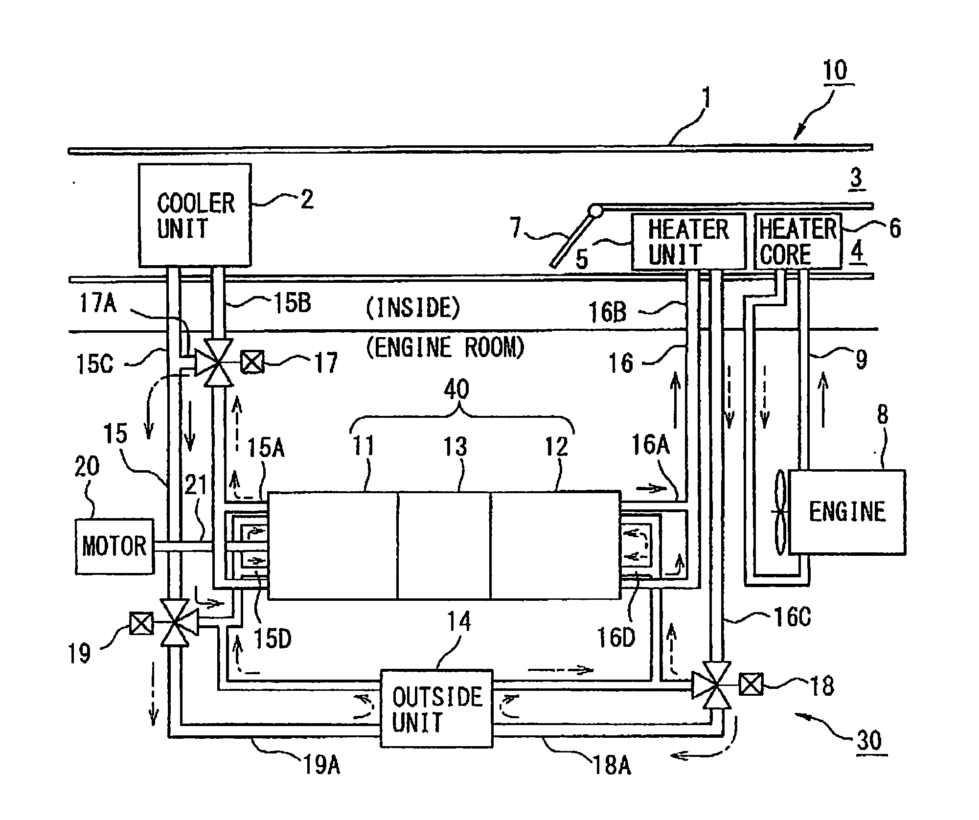
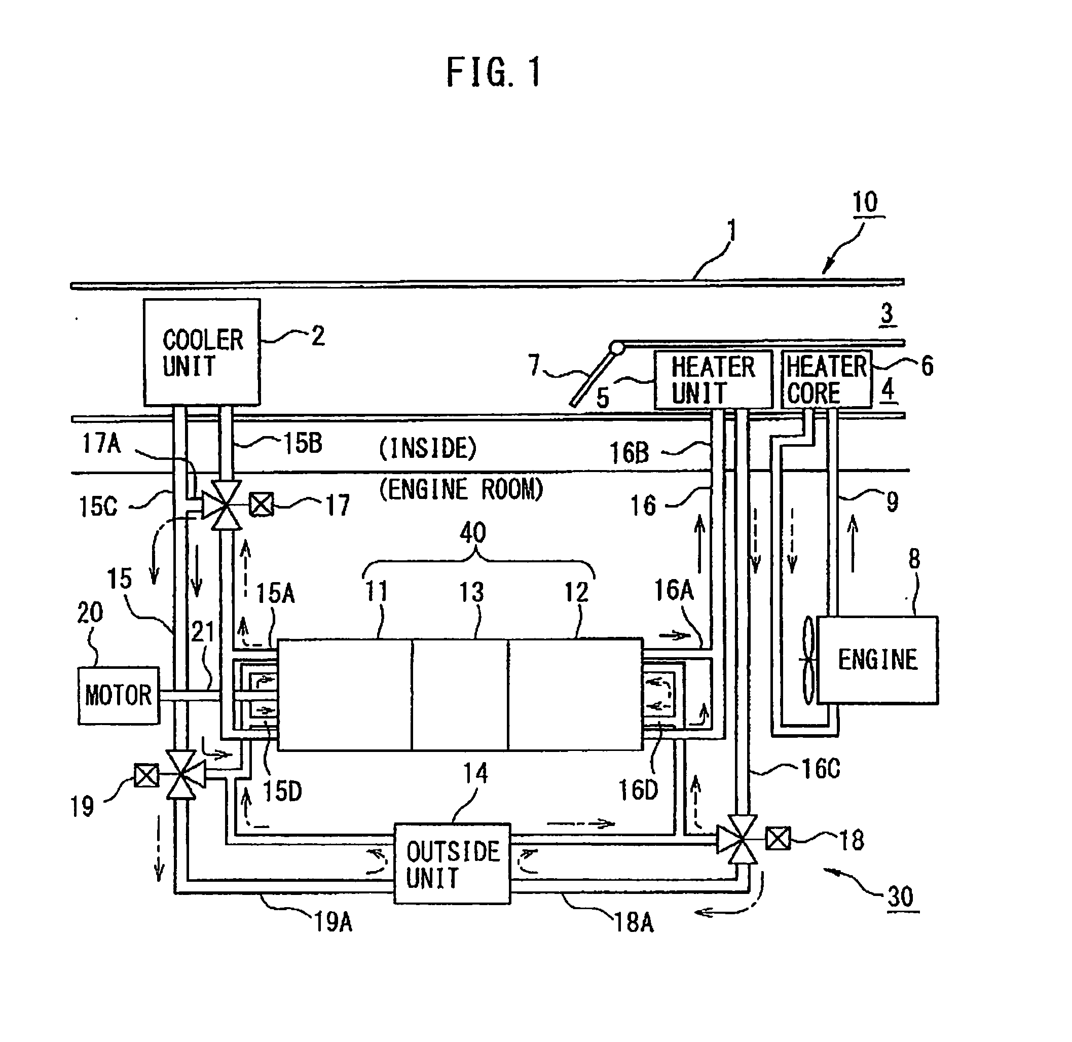
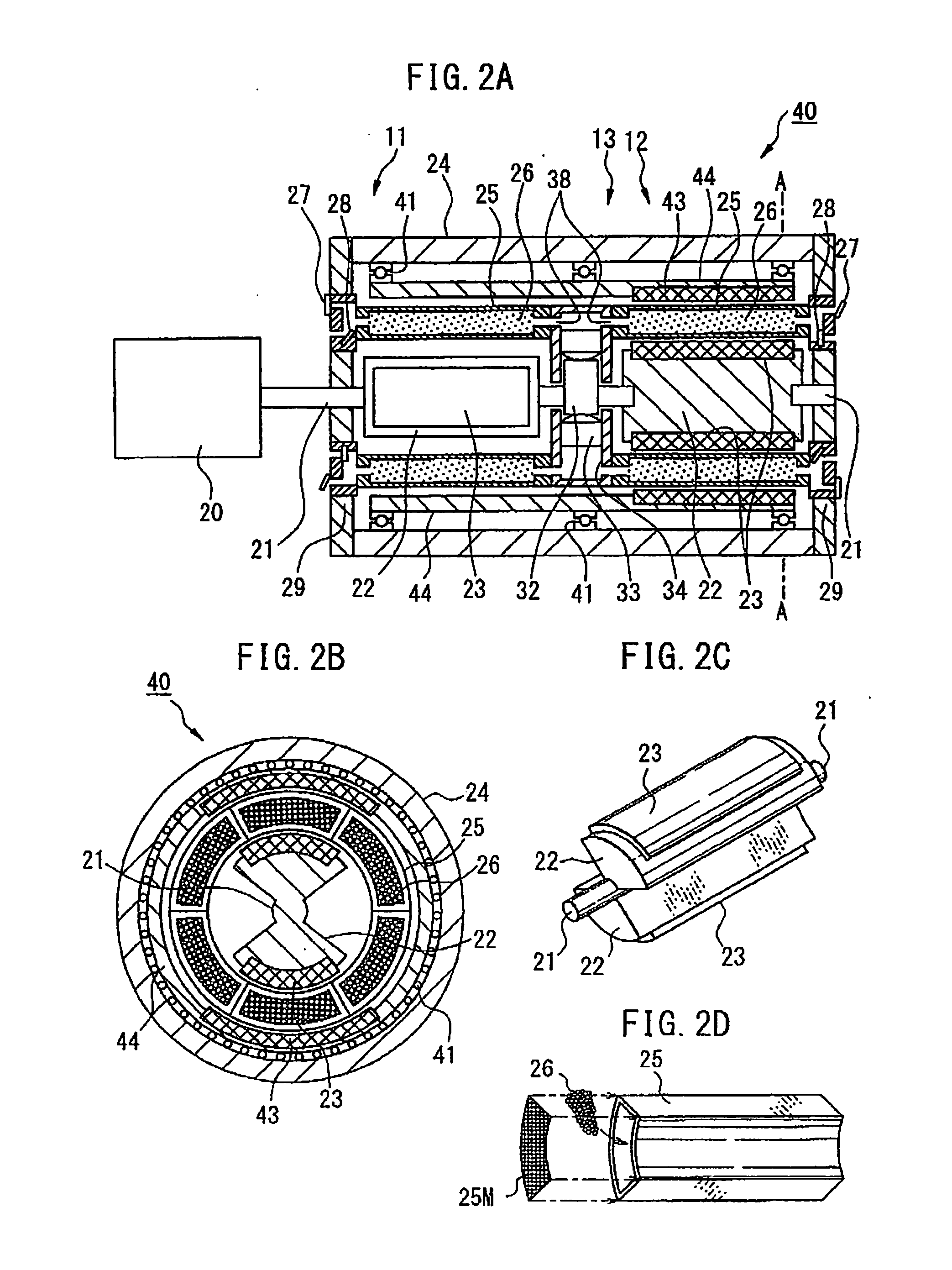
[0036]FIG. 2A is a cross-sectional view which illustrates a magnetic heat pump 40 in the magnetic heat pump system 30 which is illustrated in FIG. 1. Further, FIG. 2B is a local cross-sectional view along the line A-A of the magnetic heat pump 40 which is illustrated in FIG. 2A. Furthermore, FIG. 2C is a perspective view which illustrates one example of the configuration of a rotor 22 which is provided with magnets 23 which are illustrated in FIG. 2A, while FIG. 2D is an assembled perspective view which illustrates the configuration of one example of a material container 25 which holds the magnetocalorific effect material 26 which is illustrated in FIG. 2A.

[0037]In the first embodiment which is illustrated in FIG. 2A, for the reciprocating pump 13, a radial piston pump is used, but as the reciprocating pump 13, a swash plate compressor may also be used. The structures of the cooling water manufacturing part 11 and the warm water manufacturing part 12 which are attached to the recipr...

second embodiment

[0049]In the second embodiment as well, if the permanent magnets 23 which are attached to the outer circumferential surface of the rotor 22 rotate due to the motor 20, along with the rotation of the permanent magnets 23, the rotary magnets 43 which face the permanent magnets 23 rotate following them due to the attraction force of the magnets and therefore the yoke part 44 rotates. The intensity of the magnetic field which is applied to the magnetocalorific effect material 26 which is filled in the material containers 25 is 30 to 60% higher than the case where the permanent magnets 23 are provided only at the inside of the magnetocalorific effect material 26.

[0050]Note that, in the magnetic heat pump 40 of the second embodiment which is illustrated in FIG. 3A, as the two reciprocating pumps 13A and 13B, radial piston pumps which are provided with pistons 33A and 33B which are driven by control cams 32A and 32B are illustrated. On the other hand, as the two reciprocating pumps 13A and...

third embodiment

[0054]At the space inside the shell 51 sandwiched between the permanent magnets 53 and the permanent magnets 55, there is a container mount 57 which is not connected to the shaft 21. At the container mount 57, as illustrated in FIG. 4C, a plurality of material containers 25 in which a magnetocalorific effect material is filled are attached in a radial manner. The cross-sectional shape of material containers 25 in a direction vertical to the flow of the heat transport medium is rectangular or circular. The container mount 57 may be formed integrally with the shell 51, or a separate container mount 57 may be attached to the inside of the shell 51. At the outside and inside parts of the material containers 25, discharge / intake valve mechanisms 56 with built-in discharge valves 27 and intake valves 28 are provided. In the third embodiment, each of the discharge / intake valve mechanisms 56 at the outside is connected to the medium passage 46A which is provided with a heat exchanger 45A, w...


PUM


Abstract

A magnetic heat pump system which arranges permanent magnets at the two sides of a magnetocalorific effect material to thereby strengthen the magnetic field to improve the cooling and heating ability, which magnetic heat pump system uses first and second magnets which move inside and outside of the containers in the state facing each other to change a magnitude of a magnetic field which is applied to a plurality of containers in which a magnetocalorific effect material is stored so as to change a temperature of a heat transport medium which is made to flow through the containers by a reciprocating pump, the intensity of the magnetic field which is applied to the magnetocalorific effect material in the containers being increased to enlarge the change of temperature of the heat transport medium which is discharged from the magnetic heat pump and improve the cooling and heating efficiency.

Description

BACKGROUND OF THE INVENTION[0001]1. Field of the Invention[0002]The present invention relates to a magnetic heat pump system and to an air-conditioning system which uses that system.[0003]2. Description of the Related Art[0004]Known in the art is a magnetic heat pump system (also called a “magnetic refrigerating system”) which uses a magnetocalorific material as a work element. A magnetic heat pump system, compared with a refrigeration technique which utilizes conventional gas compression and expansion, that is, a gas heat pump system, does not use Freon or Freon alternatives, so is environmentally friendly. Further, in a magnetic heat pump system, the compression process or the expansion process using a compressor which was necessary for the gas heat pump system is unnecessary, so the energy efficiency is high. The only components which are required for a magnetic heat pump system are a pump which runs a fluid through a magnetocalorific effect material for heat exchange and a magne...

Claims


Application Information

Patent Timeline
IPC IPC(8): F25B21/00
CPCF25B21/00F25B2321/0022Y02B30/00
Inventor WATANABE, NAOKIFUSE, TAKUYAYATSUZUKA, SHINICHINISHIZAWA, KAZUTOSHIMORIMOTO, TSUYOSHI
Owner DENSO CORP
Why Eureka
Try Eureka