Laser scanning module with rotatably adjustable laser scanning assembly

Inactive Publication Date: 2013-12-12
METROLOGIC INSTR
View PDF3 Cites 83 Cited by
  • Summary
  • Abstract
  • Description
  • Claims
  • Application Information

AI Technical Summary

Benefits of technology

[0009]Another object is to provide an improved method of and apparatus for adjusting the beam folding mirror, light collection mirror, and scanning

Problems solved by technology

A major problem encountered during the manufacture of laser scanning engines described above is adjusti

Method used


Image

  • Laser scanning module with rotatably adjustable laser scanning assembly
  • Laser scanning module with rotatably adjustable laser scanning assembly
  • Laser scanning module with rotatably adjustable laser scanning assembly

Examples


Embodiment Construction

[0075]Referring to the figures in the accompanying drawings, the various illustrative embodiments of the present invention will be described in greater detail, wherein like elements will be indicated using like reference numerals.

Overview on the Method of Optical Alignment According to Principles of the Present Disclosure

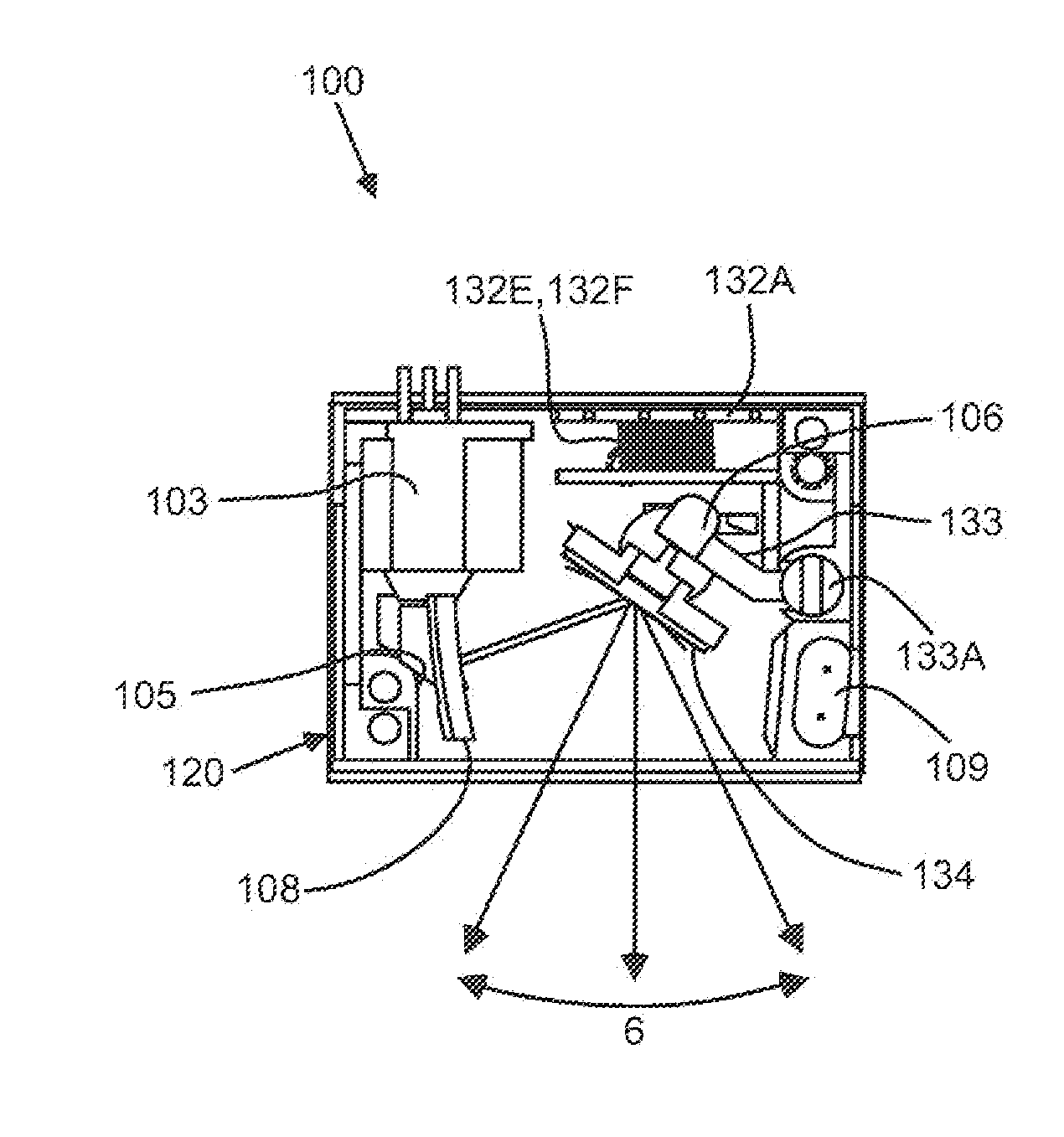
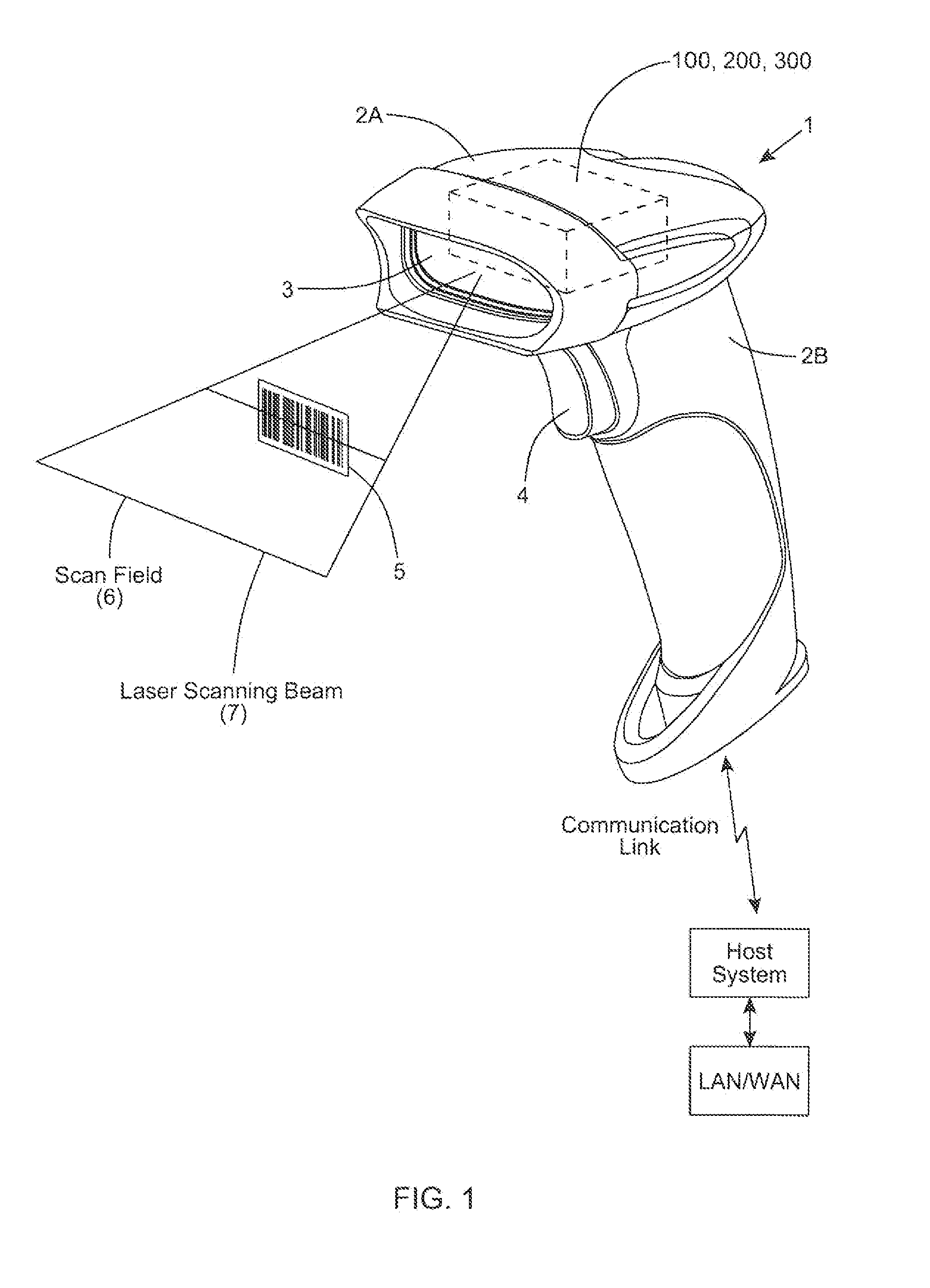
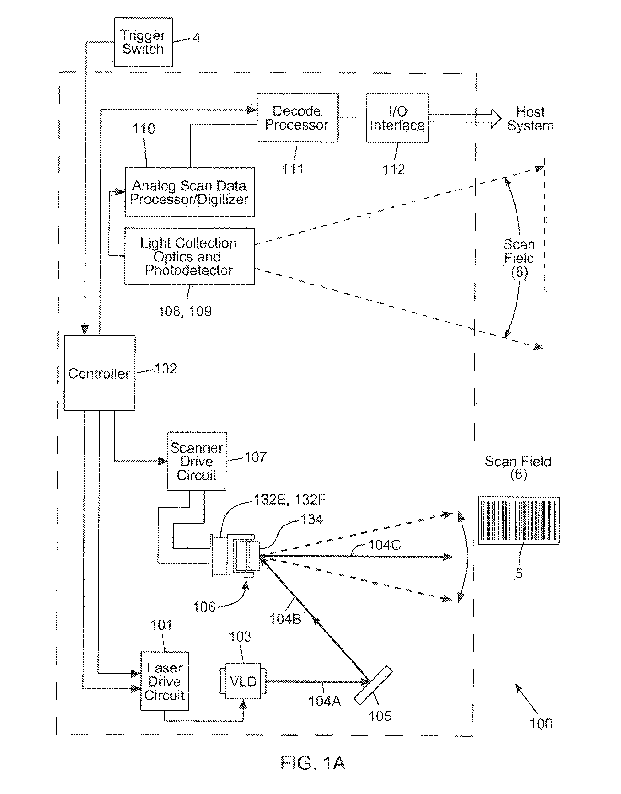
[0076]Disclosed herein is a novel laser scanning module, and a novel method of adjusting the optics therewithin during manufacture. In the general, the laser scanning module can be used in diverse kinds of laser scanning bar code symbol reading systems 1 including, but not limited to, the laser scanning modules shown in the illustrative embodiments. For purposes of illustration, FIG. 1 shows a laser scanning module (i.e. engine) 100, 200, 300 embodied in hand-supportable laser scanning system 1. However, it is understood that such laser scanning modules 100, 200 and 300 can be installed in other types of laser scanning systems, including hand-supportable, POS-projec...


PUM


Abstract

A laser scanning module employing a laser scanning assembly mounted within a module housing using a mechanism that allows the laser scanning assembly to be rotated to an angular position within the engine housing so that light collection, beam folding and light collection mirrors in the module housing are optically aligned. A PC board is mounted on a side of the housing and has a configuration of elongated apertures of open-ended and/or closed geometry, arranged in a non-parallel manner. An electromagnetic coil structure, associated with the laser scanning assembly, has a linear array of electrically-conductive pins that project through the configuration of elongated holes, at locations along the elongated holes that are determined by the angular rotation of the laser scanning assembly attained during optical alignment conditions during manufacture.

Description

BACKGROUND OF DISCLOSURE[0001]1. Field of Disclosure[0002]The present disclosure relates to improvements in optical scanning devices and more particularly to a new and improved laser scanning modules with simpler methods of assembly and optical adjustment.[0003]2. Brief Description of the State of the Art[0004]The use of laser scanning bar code symbol reading engines is well know in the art. Applications include: hand-held products; reverse-vending machines; and the like.[0005]A major problem encountered during the manufacture of laser scanning engines described above is adjusting the beam folding mirror and scanning mirror located within the housing of the laser scanning engine. During this adjustment process, carried out during manufacturing, the goal is to adjust the optical paths of the outgoing laser illumination beam and the return laser beam so that they are in desired locations, and performance is maximized.[0006]One method of achieving such alignment between the beam foldin...

Claims


Application Information

Patent Timeline
IPC IPC(8): G06K7/14
CPCG06K7/10831G06K7/10881
Inventor HENNICK, ROBERT JOHNSPUCHES, ROBERTO
Owner METROLOGIC INSTR
Why Eureka
Try Eureka