Sealing device

a sealing device and sealing technology, applied in the field of sealing devices, can solve the problems of limiting disruptions to the end of supply channels, and achieve the effect of convenient availability

Active Publication Date: 2013-12-12
VOITH PATENT GMBH
View PDF11 Cites 8 Cited by
  • Summary
  • Abstract
  • Description
  • Claims
  • Application Information

AI Technical Summary

Benefits of technology

[0017]To provide a consistent resupply of lubricant which is easily made available, the sealing element may be equipped with a manifold for several feeding channels with at least one lubricant connection. The manifold can be incorporated into the sealing element without problems and the ends can possibly be sealed off by a plug.

Problems solved by technology

The aforementioned disruptions are hereby limited to the ends of the supply channel and to potential stabilizing webs.

Method used


Image

  • Sealing device
  • Sealing device

Examples


Embodiment Construction

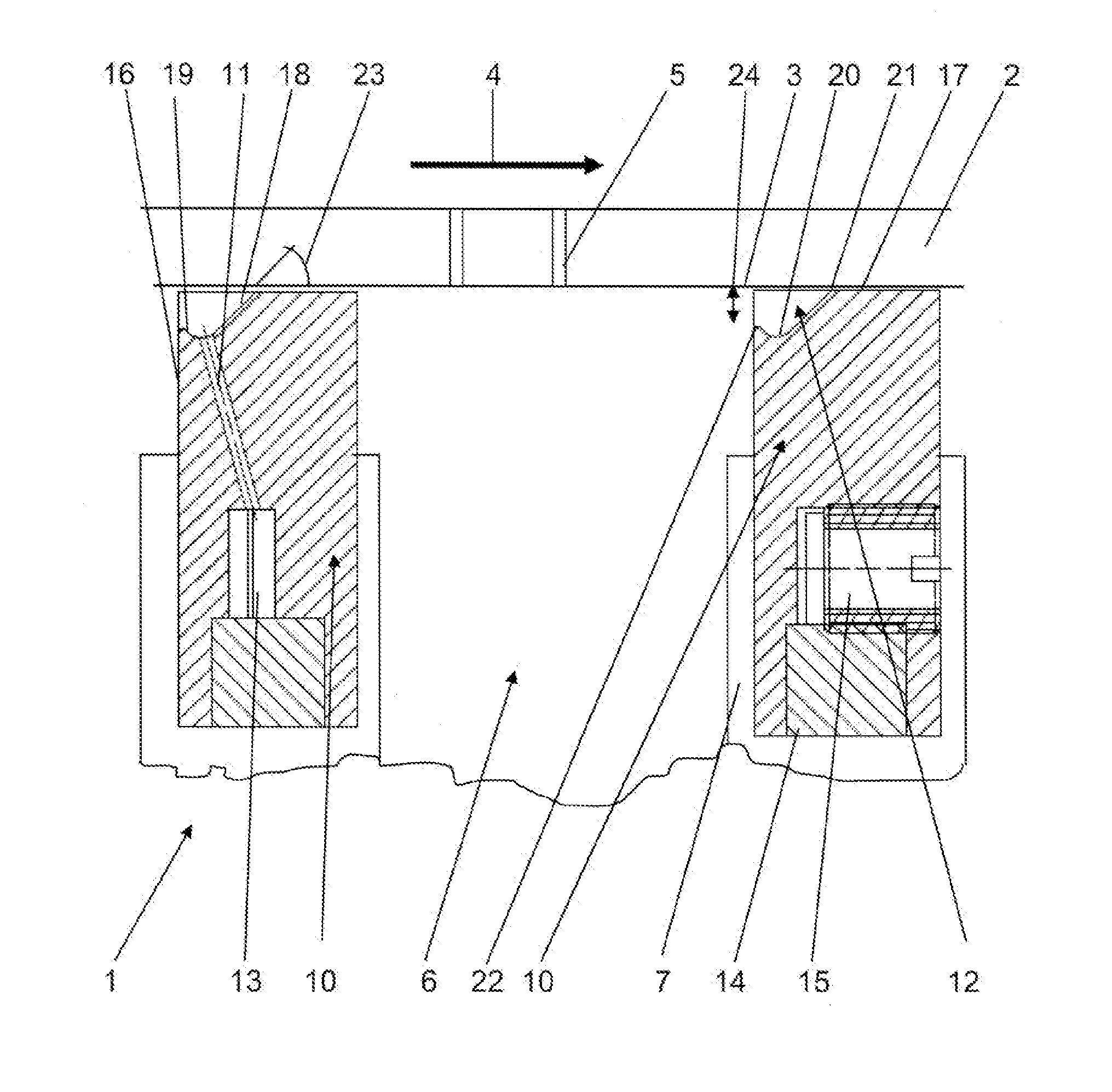
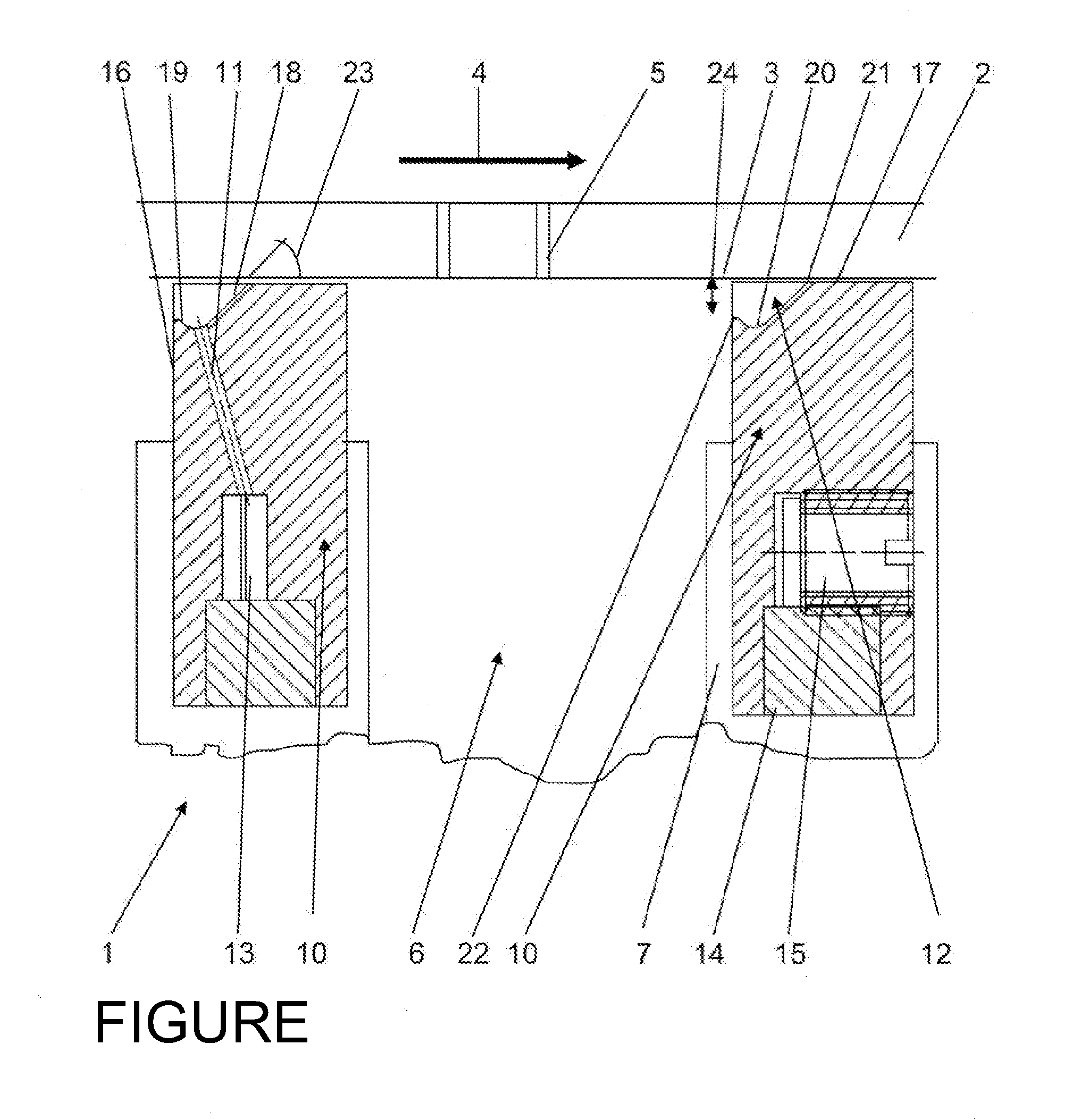
[0023]Referring now to the drawing, there is shown two sealing elements 10 of a sealing device 1 in different sectional planes which can for example be arranged inside a suction roll of a paper machine and which can interact with the inside wall 3 of roll shell 2. Through such sealing elements 10 a desired number of underpressure zones 6 having different pressure levels can be sealed. Roll shell 2 is equipped with suction holes 5 for the purpose of, for example, being able to suck off moisture from a web.

[0024]In the current example each sealing element interacts with a moving surface 3, formed by shell 2 of a suction roll equipped with suction holes 5 and which is consistent with the interior shell surface. The direction of movement of interior shell surface 3 is defined by arrow 4.

[0025]Sealing element 10 is supported in a mounting 7. These mountings are known and can include a power source which is not illustrated and which presses sealing element 10 with a defined pressure again...


PUM


Abstract

A sealing device for sealing at least one underpressure or overpressure zone adjoining a surface which is moved in a movement direction in a paper, tissue or cardboard machine, includes at least one sealing element which is located opposite the moved surface and has at least one feed channel for a lubricant. In order to considerably decrease the wear of a sealing element uniformly over the entire length thereof, the at least one feed channel ends in a supply channel, which is arranged at the beginning of the sealing element in the movement direction.

Description

CROSS REFERENCE TO RELATED APPLICATIONS[0001]This is a continuation of PCT application No. PCT / EP2012 / 051682, entitled “SEALING DEVICE”, filed Feb. 1, 2012, which is incorporated herein by reference.BACKGROUND OF THE INVENTION[0002]1. Field of the Invention[0003]The present invention relates to a sealing device for sealing at least one underpressure or overpressure zone adjoining a moving surface which is moving in a direction of travel in a paper, tissue or cardboard machine. The sealing device includes at least one sealing element which is located opposite the moving surface and has at least one feeding channel for lubricant.[0004]2. Description of the Related Art[0005]Sealing devices of this type are used in practice in the forming section as well as in the press section and / or the drying section of a respective paper machine application where among other possibilities they can be installed in suction rolls or blow rolls. Suction boxes are generally equipped with stationary inter...

Claims


Application Information

Patent Timeline
Patent Type & Authority Applications(United States)
IPC IPC(8): F16J15/16
CPCF16J15/16D21F1/50D21F3/10F16J15/168
Inventor HONOLD, JOCHEN
Owner VOITH PATENT GMBH
Why Eureka
Try Eureka