Ventilation and Cooling System for an Office Chair

a cooling system and office chair technology, applied in the field of personal ventilation and cooling, can solve the problems of uneven temperature over the space, uncomfortable people to remain in their seats without some form of local ventilation, and the surface does not provide sufficient aeration to the body, so as to increase the dissipation of body heat

Inactive Publication Date: 2013-12-12
BBREEZER
View PDF8 Cites 27 Cited by
  • Summary
  • Abstract
  • Description
  • Claims
  • Application Information

AI Technical Summary

Benefits of technology

This invention is a ventilation and cooling system for an AERON office chair. It includes an air mover, power supply and control switch. The air mover attaches to the chair's seat and is powered by a power supply unit. The control switch controls the speed of the air mover to regulate the flow of air. The system cools the hips and posterior of the person seated in the chair, helping to dissipate body heat. The system can also provide ventilation and cooling when not in use on the chair.

Problems solved by technology

This sort of regulation inevitably results in variations of the temperature over the space being regulated.
However, there are instances in which sufficiently large temperature variations arise that require local adjustments of the ambient temperature.
Or conversely, the heat generated by computers under the desks of modern office workers raises the air temperature near the floor making it uncomfortable for people to remain in their seats without some form of local ventilation.
The problem of achieving a comfortable body temperature for an office worker who spends the majority of the day seated is further compounded by insufficient body heat dissipation due to the trapping of body heat by the seating assembly.
These surfaces do not provide sufficient aeration to the body.
Similar approaches are also evident in the prior art pertaining to the auto industry, where the trapping of body heat by the seating assembly can make the operator of the vehicle uncomfortable over prolonged periods of time.
While it may be practical for an auto manufacturer to design a custom seat with ventilation and cooling features, which is then mass produced as a standard part of the vehicle, it is not practical to expect an employer to offer each employee the option to choose a bespoke chair that is outfitted with a ventilation system.
However, this approach has the drawback of potentially compromising the comfort and aesthetics of the chair.
However, it cannot cool the occupant of the chair below the ambient air temperature.

Method used


Image

  • Ventilation and Cooling System for an Office Chair
  • Ventilation and Cooling System for an Office Chair
  • Ventilation and Cooling System for an Office Chair

Examples


Embodiment Construction

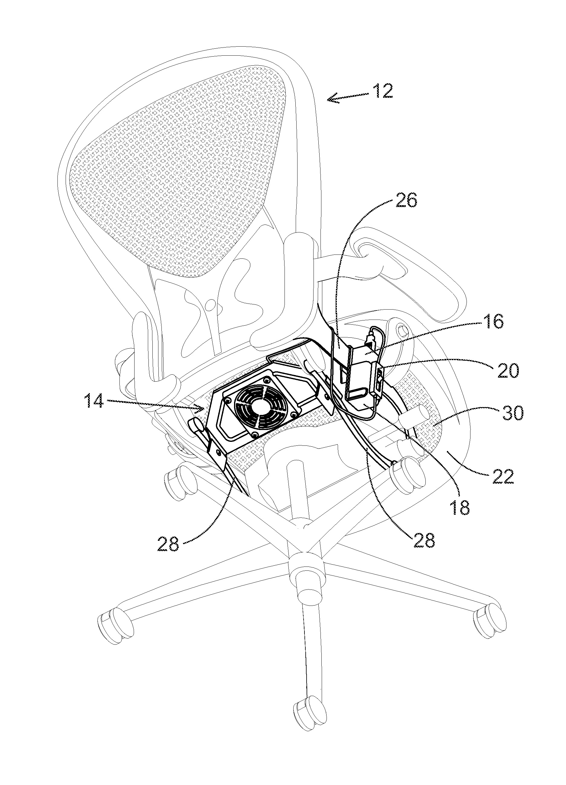
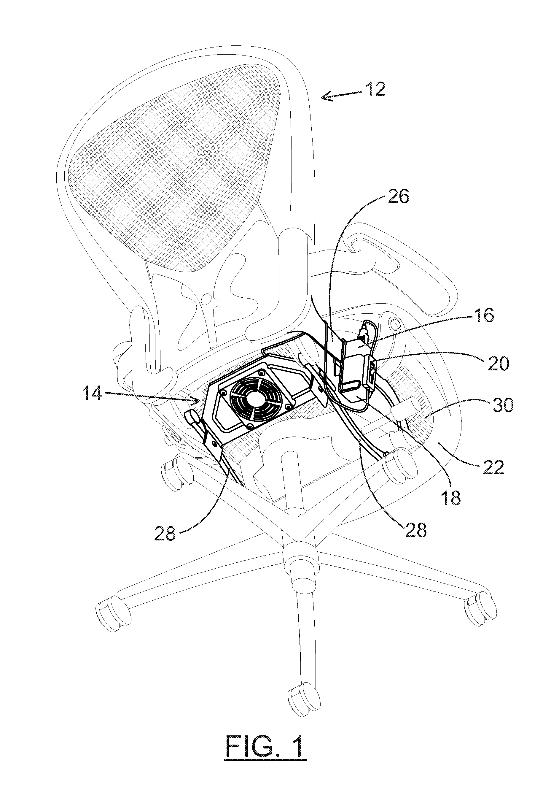
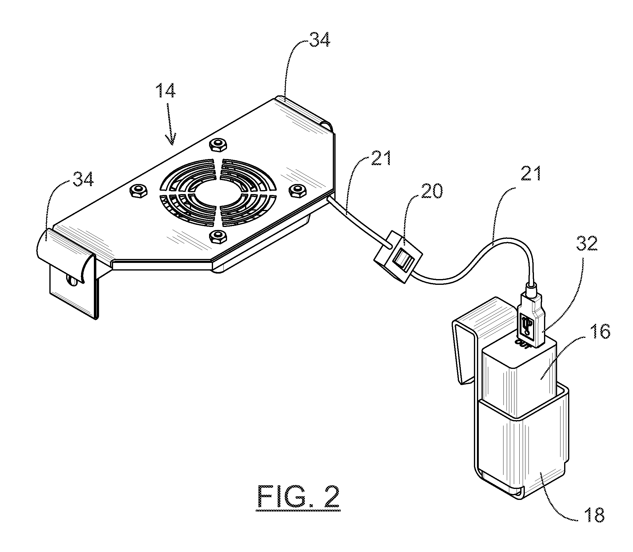
[0017]An AERON office chair 12 having a seat frame 22 and an air permeable, elastic membrane as a seat surface 30 is shown in FIG. 1. In a preferred embodiment of the present invention, an air mover 14 attaches to restraining links 28 underneath the seat frame 22 of the chair. The air mover 14 is connected to a power supply unit 16 residing in a holster 18 clipped to a horizontal bar 26, located on either the left or right hand side of the chair. Placing the power source unit on the chair eliminates the need for a power cable extending from the air mover 14 to a remote power jack, which would restrict the lateral or rotational movements of the chair. A control switch 20 adjusts the rate of airflow generated by the air mover 14. The airflow from the air mover 14 ventilates the space beneath the seat frame 22 and cools the occupant of the chair by dissipating body heat through the air permeable membrane of the seat surface 30.

[0018]A significant advantage of the present invention is t...


PUM


Abstract

A ventilation and cooling system for an AERON office chair is disclosed. It consists of an air mover, a power supply unit and a control switch. The system attaches underneath the seat of the chair. Airflow from the air mover is directed towards the seat to dissipate the body heat of the chair's occupant. The increased airflow cools the posterior and crotch regions of the person occupying the chair.

Description

CROSS-REFERENCE TO RELATED APPLICATIONS[0001]This application claims the priority benefit of U.S. Provisional Patent application No. 61 / 657,856, filed on Jun. 10, 2012.BACKGROUND OF THE INVENTION[0002]The present invention is in the field of personal ventilation and cooling. Specifically, it is a ventilation and cooling system for an office chair.[0003]Ventilation and climate control in office buildings is usually accomplished through centralized units that regulate the temperature of large volumes of air. This sort of regulation inevitably results in variations of the temperature over the space being regulated. On average, the variations are minor and can be ignored. However, there are instances in which sufficiently large temperature variations arise that require local adjustments of the ambient temperature. For example, the person under a vent feels the need to plug in a heater during the summer months when the air conditioning is in full blast. Or conversely, the heat generated ...

Claims


Application Information

Patent Timeline
IPC IPC(8): A47C7/74
CPCA47C7/742A47C7/744
Inventor ANTONOV, RADOSLAV DIMITROVANTONOV, DIMITAR EMILOV
Owner BBREEZER
Why Eureka
Try Eureka