Method for operating a regenerative braking system of a vehicle and control unit for a regenerative braking system of a vehicle

a regenerative braking and control unit technology, applied in the direction of braking systems, instruments, analogue processes for specific applications, etc., can solve the problems of m_gen applied generator braking torque, and achieve the effect of increasing the actual brake pressure over time, and reducing the generator braking torqu

Active Publication Date: 2013-12-12
ROBERT BOSCH GMBH
View PDF3 Cites 9 Cited by
  • Summary
  • Abstract
  • Description
  • Claims
  • Application Information

AI Technical Summary

Benefits of technology

[0010]The present invention permits a brake pressure buildup in the at least one brake circuit and / or the at least one wheel brake cylinder exclusively by operation of the at least one brake fluid delivery mechanism at relatively low delivery rates to compensate for the generator braking action being omitted in controlling the braking system out of the first braking mode into the second braking mode. A pressure buildup which is low in noise and vibration is implementable due to operation of the at least one brake fluid delivery mechanism at relatively low delivery rates, e.g., low pump rotational speeds. There is thus no need for applying insulation to shield the occupants of the vehicle from a noise burden and / or a vibration burden during the pressure buildup. In addition, the delivery rate implemented by the at least one brake fluid delivery mechanism should be optimized by the present invention with regard to a suppressed / low noise level as well as with regard to the desired high demands regarding dynamics and efficiency.
[0011]Furthermore, the actual brake pressure, which is implementable via the present invention in the at least one brake circuit / wheel brake cylinder, is implementable within a relatively short time interval, so that the point in time for termination of a purely regenerative brake phase may be extended. A high regenerative efficiency is advantageously achievable due to the comparatively long regenerative braking of the vehicle, which is implementable via the present invention.
[0013]In one advantageous specific embodiment of the method, during the activation of the at least one brake fluid delivery mechanism via the established or predefined setpoint delivery output variable, a setpoint generator braking torque of the generator is established while taking into account the total setpoint braking torque and a variable with respect to a hydraulic brake pressure built up in the at least one wheel brake cylinder and / or the at least one brake circuit. Subsequently, the generator braking torque of the generator is adjusted similarly. In this way the high dynamics and good regulability of the generator in comparison with the properties of the hydraulic portions of the operated braking system may be utilized for more reliably maintaining the total setpoint braking torque. In particular in this way the hydraulic pressure in the at least one brake circuit and / or in the at least one wheel brake cylinder may be built up volumetrically at comparatively low pump speeds, in particular at a low constant pump speed, for the desired masking of the generator braking action being omitted. The generator may be controlled / regulated easily in such a way that the generator braking torque is reduced in accordance with the brake pressure already built up, i.e., the hydraulic braking torque induced in this way.
[0014]For example, a setpoint rotational speed which is constant over time and / or an operating current which is constant over time may be provided as the setpoint delivery output variable(s) on at least one pump as the at least one brake fluid delivery mechanism. Thus, in particular despite having to overcome air gaps / tolerances and a high elasticity of the braking system at the start of a brake pressure buildup, the present invention enables the advantageous actual brake pressure by operation of the at least one pump at a constant pump speed. The pump speed, which may thus be maintained at a constant level, may be established in such a way that the occurrence of noise / vibration is reliably suppressed.
[0017]In one advantageous refinement, during the activation of the at least one brake fluid delivery mechanism, the generator braking torque of the generator is reduced at a negative slope, the absolute value of which increases over time, via the established or predefined setpoint delivery output variable, so that a time characteristic of the generator braking torque corresponds to a regressively declining braking torque graph. Furthermore, the setpoint delivery output variable may also be established or predefined in accordance with a progressively increasing pressure buildup graph as the setpoint brake pressure having the setpoint pressure rise which increases over time. The increase in the actual brake pressure over time and the decrease in the generator braking torque over time may thus be advantageously adapted to one another via easily implementable method steps. This ensures reliably maintaining the predefined total setpoint braking torque despite the masking implemented.
[0018]For example, the braking system may be operated in a fully regenerative braking mode as the first braking mode in which the first regenerative portion is equal to 100%. In addition, the generator braking torque may be reduced to zero while the braking system is controlled out of the first braking mode into the second braking mode, the braking system then being operated in a fully hydraulic braking mode as the second braking mode, in which the second regenerative portion is equal to 0%. The present invention thus permits an advantageous transition from the fully regenerative braking mode to the fully hydraulic braking mode while reliably maintaining the predefined total setpoint braking torque at the same time.

Problems solved by technology

However, to protect the generator, it is usually necessary to reduce the applied generator braking torque M_gen to zero before the vehicle comes to a standstill.

Method used


Image

  • Method for operating a regenerative braking system of a vehicle and control unit for a regenerative braking system of a vehicle
  • Method for operating a regenerative braking system of a vehicle and control unit for a regenerative braking system of a vehicle
  • Method for operating a regenerative braking system of a vehicle and control unit for a regenerative braking system of a vehicle

Examples


Embodiment Construction

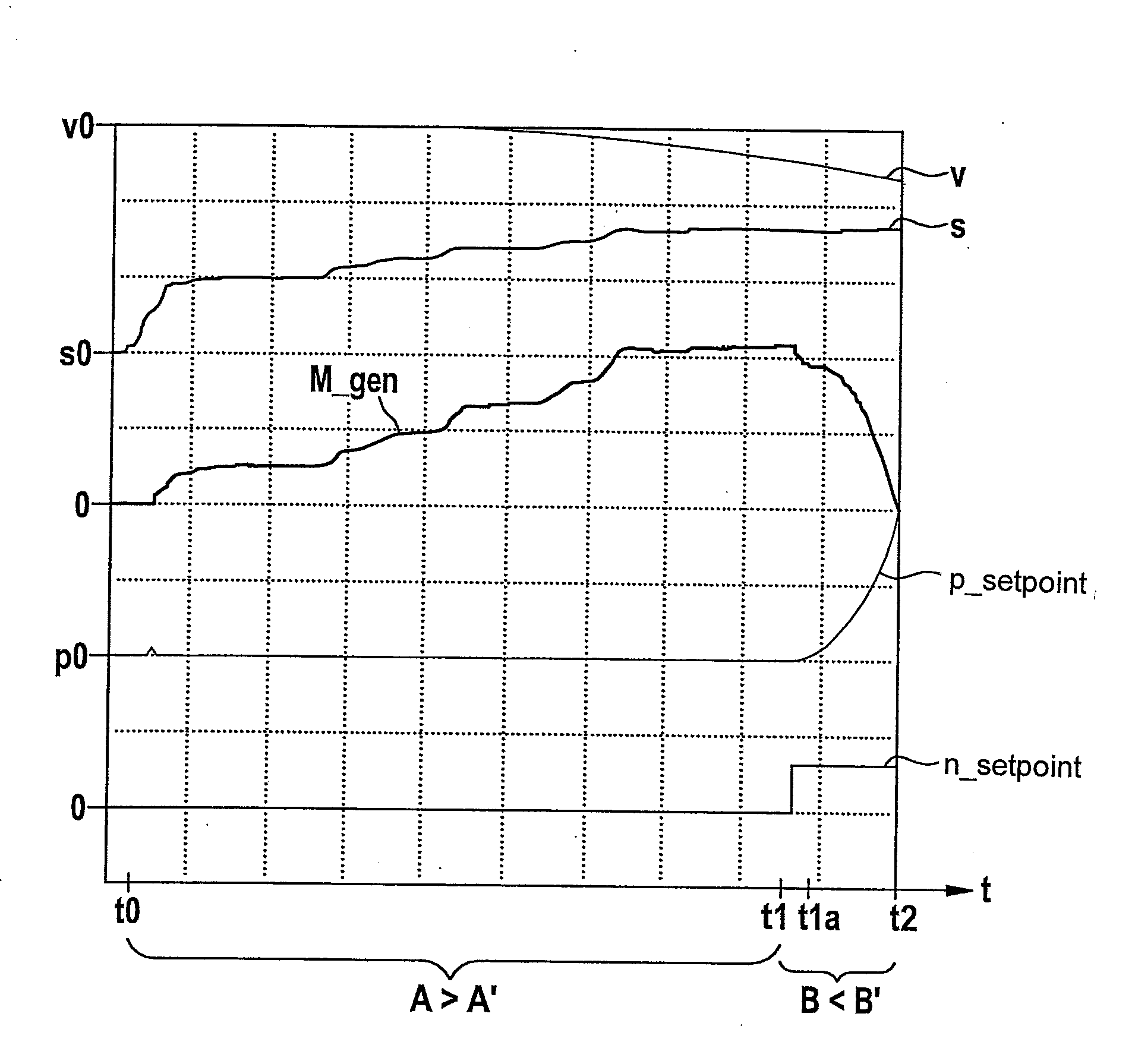
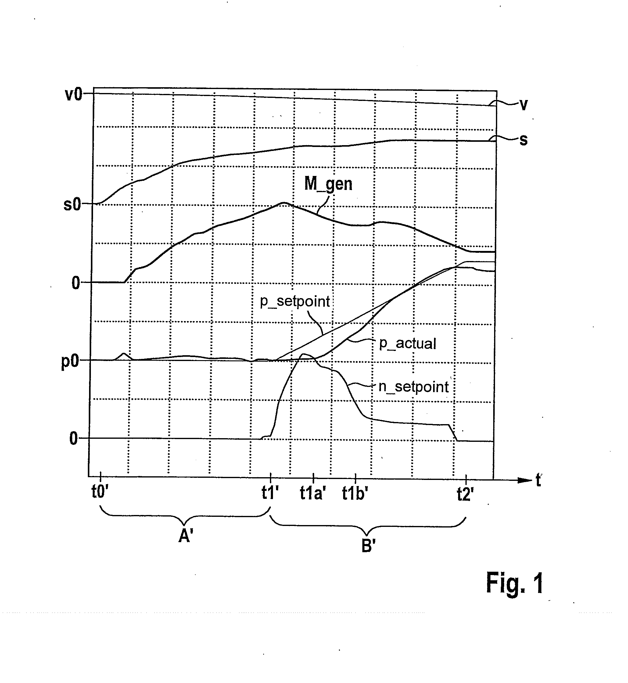
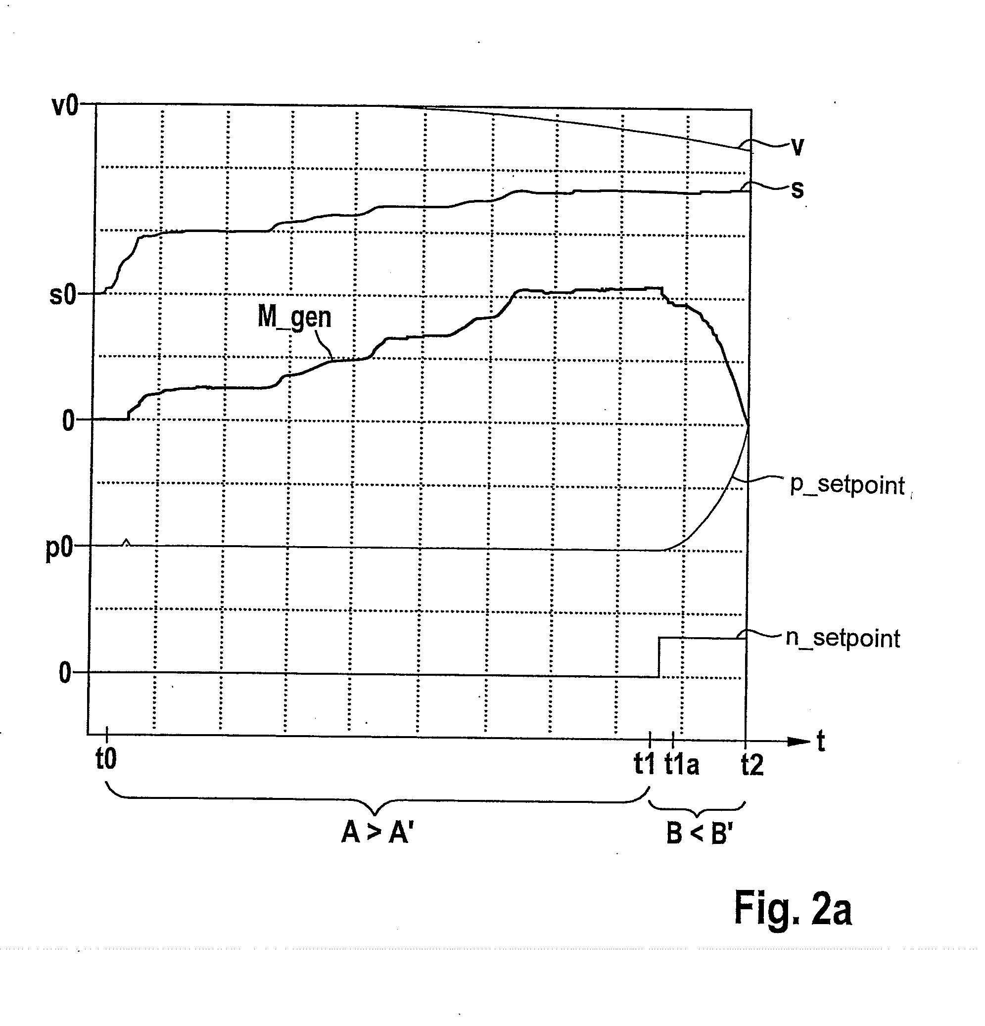
[0025]FIGS. 2a and 2b show coordinate systems for illustrating the method for operating a hydraulic braking system of a vehicle.

[0026]The method represented schematically in FIG. 2a is implementable via a plurality of braking systems of different types. The implementability of this method is therefore not limited to a certain design of the braking system used here for this purpose. In particular the coordinate system of FIG. 2b represents only a pressure-volume characteristic line k of a braking system, for which the implementation of this method is particularly advantageous. However, the implementability of this method is not limited to such a pressure-volume characteristic line k of the braking system used for this purpose.

[0027]FIG. 2b represents a pressure-volume characteristic line k of a regenerative braking system for which the use / implementation of the method described below is particularly advantageous. The abscissa of the coordinate system in FIG. 2b indicates a brake flui...


PUM


Abstract

A method / controller for operating a vehicle regenerative braking system by operating in a first braking mode, in which a generator braking torque of a generator is not zero and is equal to a first regenerative portion predefined for the first mode, and controlling the system out of the first mode into a second braking mode having a second regenerative portion, which is smaller than the first portion, so that brake fluid is pumped out of a storage volume of the system into at least one wheel brake cylinder and / or at least one brake circuit of the system via at least one brake fluid delivery mechanism; by activating the delivery mechanism via a setpoint delivery output variable, which is established / predefined for a setpoint brake pressure having a setpoint pressure rise which increases over time, so that an actual brake pressure having an actual pressure rise increase over time is built up.

Description

RELATED APPLICATION INFORMATION[0001]The present application claims priority to and the benefit of German patent application no. 10 2012 209 522.5, which was filed in Germany on Jun. 6, 2012, the disclosure of which is incorporated herein by reference.FIELD OF THE INVENTION[0002]The present invention relates to a method for operating a regenerative braking system of a vehicle. In addition, the present invention relates to a control unit for a regenerative braking system of a vehicle.BACKGROUND INFORMATION[0003]German patent document DE 10 2009 001 401 A1 discusses a braking system for a vehicle, which may be equipped with a generator. FIG. 1 shows a coordinate system to illustrate a traditional mode of operation of such a braking system having a generator. The abscissa of the coordinate system in FIG. 1 is time axis t.[0004]Starting at a point in time t0′, a driver of a vehicle braked according to the traditional mode of operation actuates a brake actuating element, e.g., a brake pe...

Claims


Application Information

Patent Timeline
Patent Type & Authority Applications(United States)
IPC IPC(8): B60T13/58
CPCB60T13/586B60T1/10B60T8/4054B60T8/4072B60T8/4872B60T2270/604B60T8/17B60W10/18B60W10/24B60W10/26
Inventor STRENGERT, STEFANKUNZ, MICHAELDROTLEFF, DIRK
Owner ROBERT BOSCH GMBH
Why Eureka
Try Eureka