Antenna device and portable wireless terminal equipped with same
- Summary
- Abstract
- Description
- Claims
- Application Information
AI Technical Summary
Benefits of technology
Problems solved by technology
Method used
Image
Examples
embodiment 1
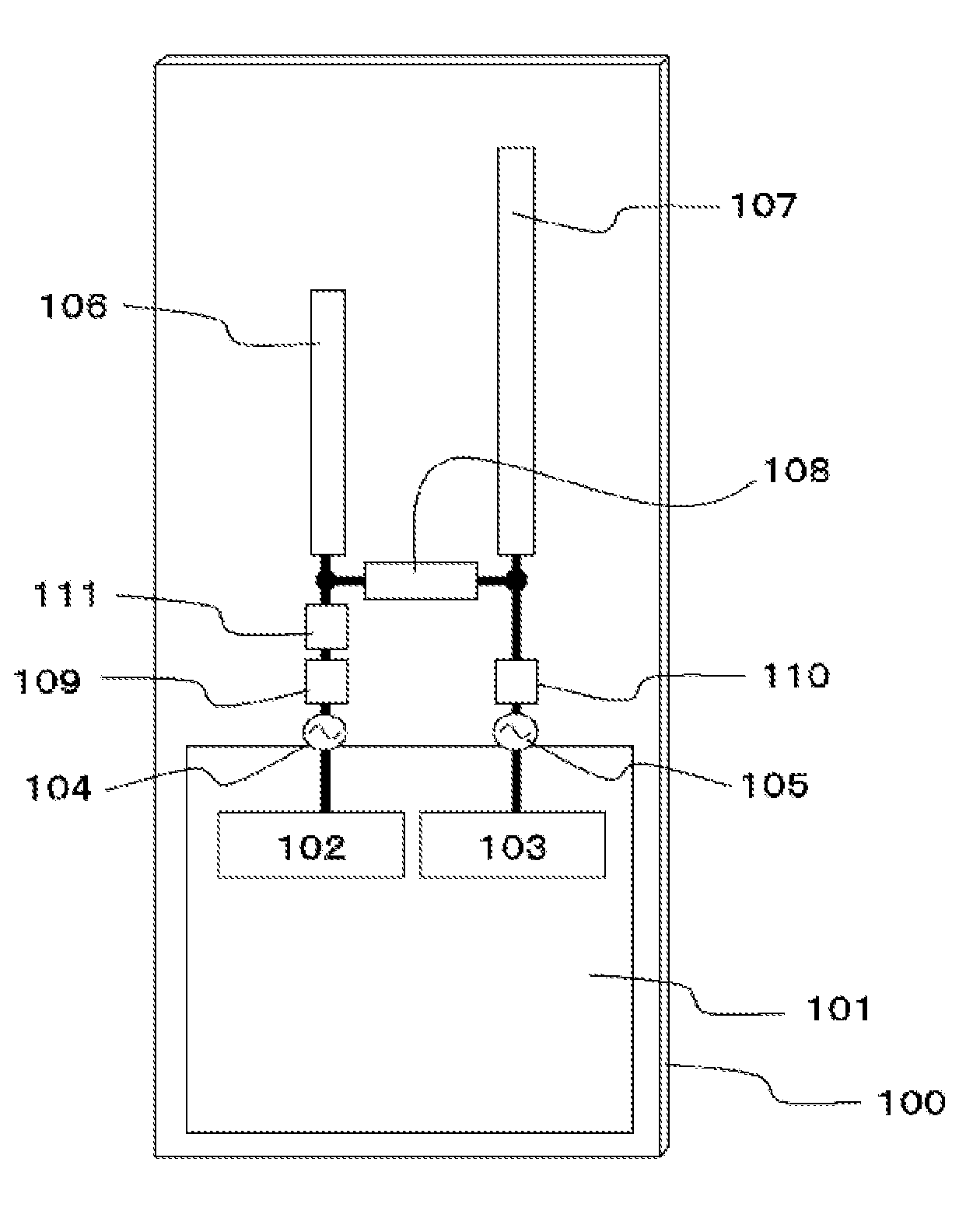
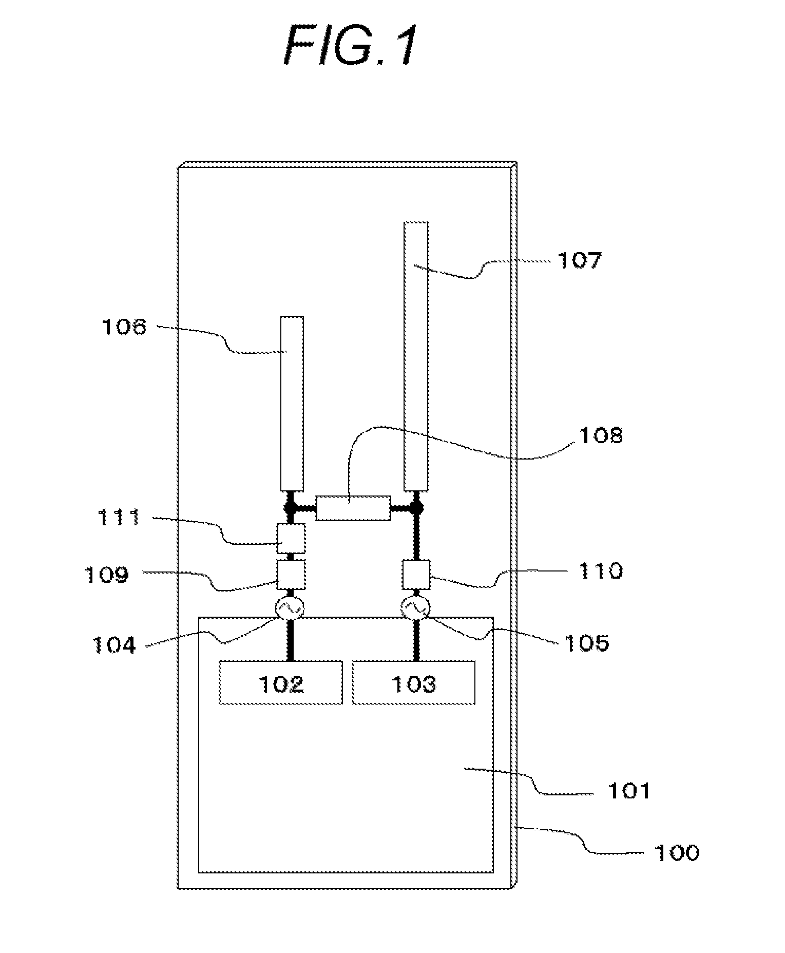
[0040]FIG. 1 shows a configuration of a portable wireless terminal according to a first embodiment of the present invention. As shown in FIG. 1, a first radio circuit unit 102 is formed on a circuit board 101 which is disposed inside the portable wireless terminal 100. A first antenna element 106 which is made of a conductive metal is supplied with a high-frequency signal via a first feeding portion 104. The first antenna element 106 is given such an electrical length as to operate in a first frequency band, for example, a length that is equal to ¼ of the wavelength of the center frequency of the first frequency band. A second radio circuit unit 103 is also formed on the circuit board 101, and a second antenna element 107 which is made of a conductive metal is supplied with a high-frequency signal via a second feeding portion 105. The second antenna element 107 is given such an electrical length as to operate in both of a first frequency band and a second frequency band, for example...
embodiment 2
[0071]FIG. 9 shows a configuration of a portable wireless terminal according to a second embodiment of the present invention. Items in FIG. 9 having the same ones in FIG. 1 are given the same symbols as the latter and will not be described.
[0072]As shown in FIG. 9, the first feeding portion 104 and the second feeding portion 105 are disposed so as to be distant from each other in the longitudinal direction of the portable wireless terminal 100, the second antenna element 107 is bent approximately at 90° to the side that is opposite to the first antenna element 106 (i.e., so as to extend in the width direction), and the first connection circuit 108 is disposed at any position that is located between the approximately-parallel-extending portions of the first antenna element 106 and the second antenna element 107.
[0073]With the above configuration, the degree of freedom of designing is increased. In the first frequency band, a high degree of isolation is secured by lowering the degree ...
embodiment 3
[0074]FIG. 10 shows a configuration of a portable wireless terminal according to a third embodiment of the present invention. Items in FIG. 10 having the same ones in FIG. 1 are given the same symbols as the latter and will not be described.
[0075]In FIG. 10, the operation frequencies of the first antenna element 106 are made the first frequency band and a third frequency band that is higher than the first frequency band. And the operation frequencies of the second antenna element 107 are made the first frequency band and a second frequency band that is lower than the first frequency band. A third frequency band cutoff circuit 112 is disposed between the second antenna element 107 and the second impedance matching circuit 110.
[0076]With the above configuration, in the first frequency band, a high degree of isolation is secured by lowering the degree of coupling. In the second frequency band and the third frequency band, high-gain performance can be realized by increasing the antenna ...
PUM
 Abstract
Description
Claims
Application Information
 - R&D
- Intellectual Property
- Life Sciences
- Materials
- Tech Scout
- Unparalleled Data Quality
- Higher Quality Content
- 60% Fewer Hallucinations
Browse by: Latest US Patents, China's latest patents, Technical Efficacy Thesaurus, Application Domain, Technology Topic, Popular Technical Reports.
© 2025 PatSnap. All rights reserved.Legal|Privacy policy|Modern Slavery Act Transparency Statement|Sitemap|About US| Contact US: help@patsnap.com


