Slab laser amplifier and laser output method

A technology of laser amplifiers and slabs, which is applied to lasers, laser components, phonon exciters, etc., can solve the problems of low pump gain utilization and large folding angles, and achieve the goals of reducing thermal effects, small width, and improving utilization Effect

Inactive Publication Date: 2015-02-04
LASER FUSION RES CENT CHINA ACAD OF ENG PHYSICS
View PDF6 Cites 4 Cited by
  • Summary
  • Abstract
  • Description
  • Claims
  • Application Information

AI Technical Summary

Problems solved by technology

[0003] In the existing slab laser amplifier system, there is still the problem of how to dissipate heat more efficiently; the input laser is a Z-shaped path inside the slab laser crystal, and its folding angle is generally large, and the utilization rate of the pump gain is low

Method used


Image

  • Slab laser amplifier and laser output method
  • Slab laser amplifier and laser output method
  • Slab laser amplifier and laser output method

Examples


Embodiment 1

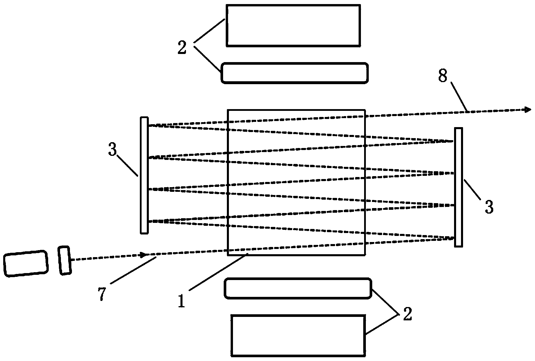
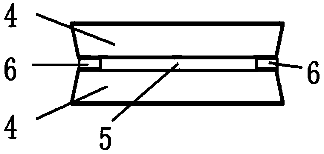
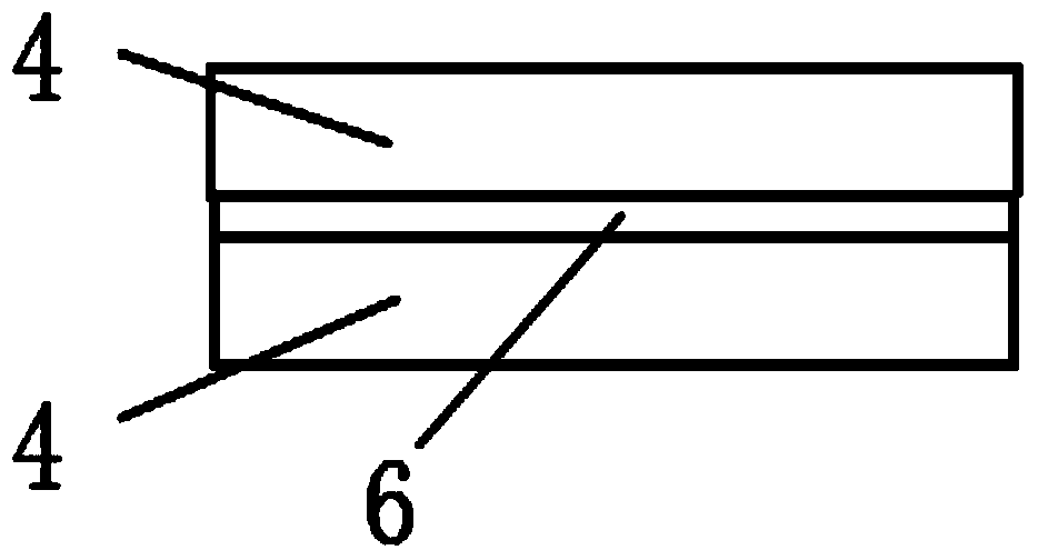
[0036] Such as Figure 1 to Figure 3 As shown, a slab laser amplifier includes a gain medium module 1 and a pump module 2. The gain medium module 1 includes a laser crystal and two cooling heat sinks 4, and the two cooling heat sinks 4 are respectively fixed on the width of the laser crystal. On both sides of the side; the pump module 2 is provided with two; also includes a mirror module, the mirror module includes two mirrors 3, located on the left and right sides of the gain medium module 1, the two pumps Module 2 is located on both sides of the front and back of gain medium module 1, and the pump laser light can directly enter gain medium module 1 without passing through a plane mirror, and then enter gain medium module 1, which reduces the energy loss of pump laser light; The thickness of the laser crystal is 0.5-1.5 mm. Compared with the prior art, the thickness of the laser crystal is smaller, which is beneficial to the heat dissipation of the laser crystal and enhances ...

Embodiment 2

[0038] Such as Figure 1 to Figure 3According to a slab laser amplifier described in Embodiment 1, the length and width of the laser crystal are greater than the thickness, the length of the laser crystal is 5-1000 mm, and the width is 5-500 mm. The non-doped laser crystal 6 has a width of 0.5 to 1.5mm; the non-doped laser crystal 6 is a yttrium aluminum garnet crystal, and the doped laser crystal 5 is a neodymium-doped yttrium aluminum garnet crystal or a ytterbium-doped yttrium aluminum garnet crystal or the aforementioned The non-doped laser crystal 6 is yttrium acid crystal, the doped laser crystal 5 is neodymium-doped yttrium vanadate crystal, and the doped laser crystal 5 and the non-doped laser crystal 6 are homogeneous substrates, so that the doped laser crystal 5 and the non-doped laser crystal Glue-free bonding can be realized between the laser crystals 6; a layer of indium is placed between the laser crystal and the cooling heat sink 4, and indium has a strong heat ...

Embodiment 3

[0040] Such as Figure 1 to Figure 3 According to a slab laser amplifier described in Embodiment 2, the two reflectors 3 are flat mirrors, and the inner surfaces of the two reflectors 3 are coated with a film with high reflectivity for the input seed laser 7-band , ensuring the multiple reflections of the input seed laser 7, preventing the input seed laser from being transmitted through the reflector 3, thereby causing energy loss; the two reflectors 3 are parallel to the side of the gain medium module 1, preventing the input seed laser 7 from being reflected during the reflection process A larger incident angle is formed in the middle, thereby reducing the number of incidents; the two reflectors 3 are centered on the central axis perpendicular to the two reflectors 3, and there is a certain deflection angle, and the deflection clamp between the two reflectors 3 The angle is 1′~100′, avoiding the formation of a flat cavity resonant structure and preventing laser self-excited o...


PUM


Abstract

The invention relates to a slab laser amplifier and a laser output method. The slab laser amplifier comprises a gain dielectric module, pumping modules, and a reflector module, wherein the reflector module comprises two reflectors which are located on the left and right sides of the gain dielectric module; the pumping modules are located on the front and rear sides of the gain medium module; laser crystals are 0.5-1.5mm thick and include one doped laser crystal and two non-doped laser crystals; the two non-doped laser crystals are bonded to the two long and high surfaces of the doped laser crystal without adhesive, respectively, and arranged in parallel with the doped laser crystal; after seed laser is incident into the laser crystals at a certain angle, the seed laser is reflected back and forth between the reflectors, and meanwhile, passes through the laser crystals between the reflectors, and finally, the power amplified laser can be output. The bonded laser crystals of an ultrathin slab structure are taken as the gain dielectric of the slab laser amplifier, the thermal effect of the laser crystals is reduced and the gain effect of the gain dielectric is improved; high-output power and high-beam quality continuous or pulse laser amplified output can be obtained.

Description

technical field [0001] The invention relates to the technical field of solid-state laser amplifiers, in particular to a slab laser amplifier and a laser output method thereof. Background technique [0002] Both the laser amplifier and the laser (oscillator) are based on the same physical process of "optical amplification by stimulated radiation", the only difference is that the laser amplifier has no resonant cavity. Laser amplifiers can obtain high output power and high beam quality laser beams; however, the two indicators of high output power and high beam quality are a contradictory process in the laser, and it is difficult to meet them at the same time. In the laser amplifier system, a seed laser beam with high beam quality and low output power is generally included as the input laser, and the input laser is then amplified by a laser amplifier to obtain a laser output with high output power and high beam quality. [0003] In the existing slab laser amplifier system, the...

Claims


Application Information

Patent Timeline
Patent Type & Authority Applications(China)
IPC IPC(8): H01S3/042H01S3/06H01S3/094H01S3/16H01S3/10
Inventor 康民强邓颖张永亮许党朋田小程粟敬钦王琳张锐王方朱启华郑万国
Owner LASER FUSION RES CENT CHINA ACAD OF ENG PHYSICS
Why Eureka
Try Eureka