Coordinated illumination and image signal capture for enhanced signal detection

a signal detection and image signal technology, applied in the field of image signal capture and processing, can solve the problems of limiting the range of colors that can be used in the printing of barcodes and be detected with the scanner, and the limited use of color to convey data signals, so as to achieve the effect of reducing the cost of the scanner

Active Publication Date: 2013-12-12
DIGIMARC CORP
View PDF5 Cites 161 Cited by
  • Summary
  • Abstract
  • Description
  • Claims
  • Application Information

AI Technical Summary

Benefits of technology

[0003]Conventional barcode scanners use single color illumination consisting of a red light emitting diode (LED). This minimizes the cost of the scanner but limits...

Problems solved by technology

This minimizes the cost of the scanner but limits the range of colors that can be used in the printed barcode and be detected with the scanner.
A similar problem occurs when using the scanner to read digital watermarks.
Red is also more distracting because it does not blend in with the natural ambient light in the room.
Thus, when implementing image signal coding in scanning hardware with white illumination and a monochrome sensor, the use of color to convey data signals is more limited, as the monochrome sensor will only capture luminance changes unde...

Method used


Image

  • Coordinated illumination and image signal capture for enhanced signal detection
  • Coordinated illumination and image signal capture for enhanced signal detection
  • Coordinated illumination and image signal capture for enhanced signal detection

Examples


Embodiment Construction

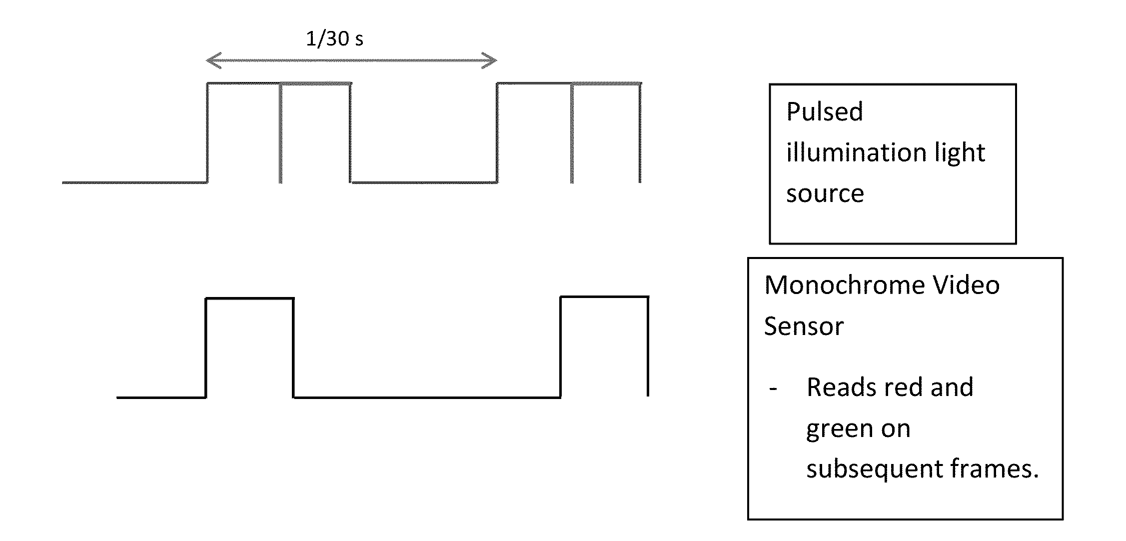
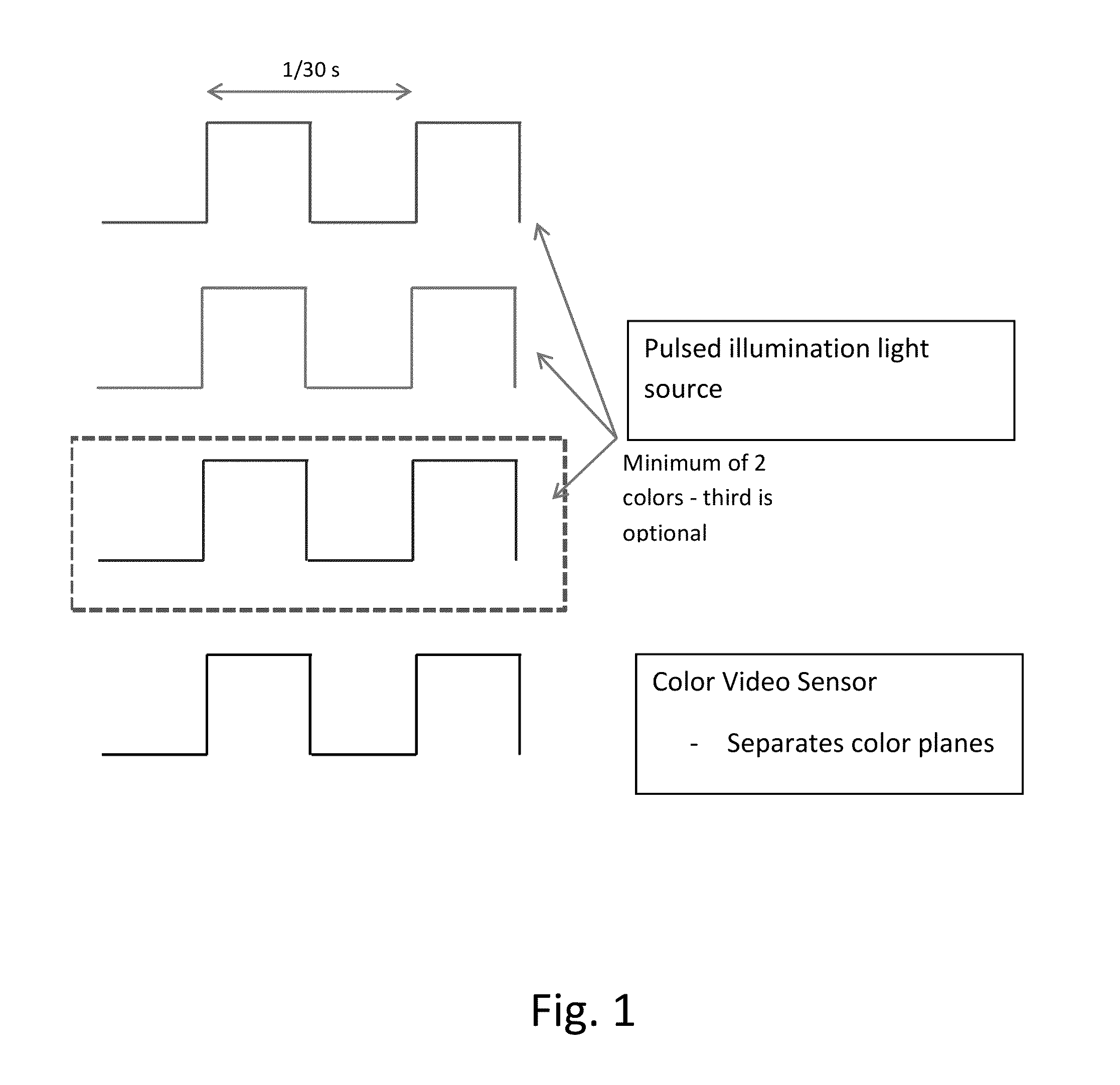
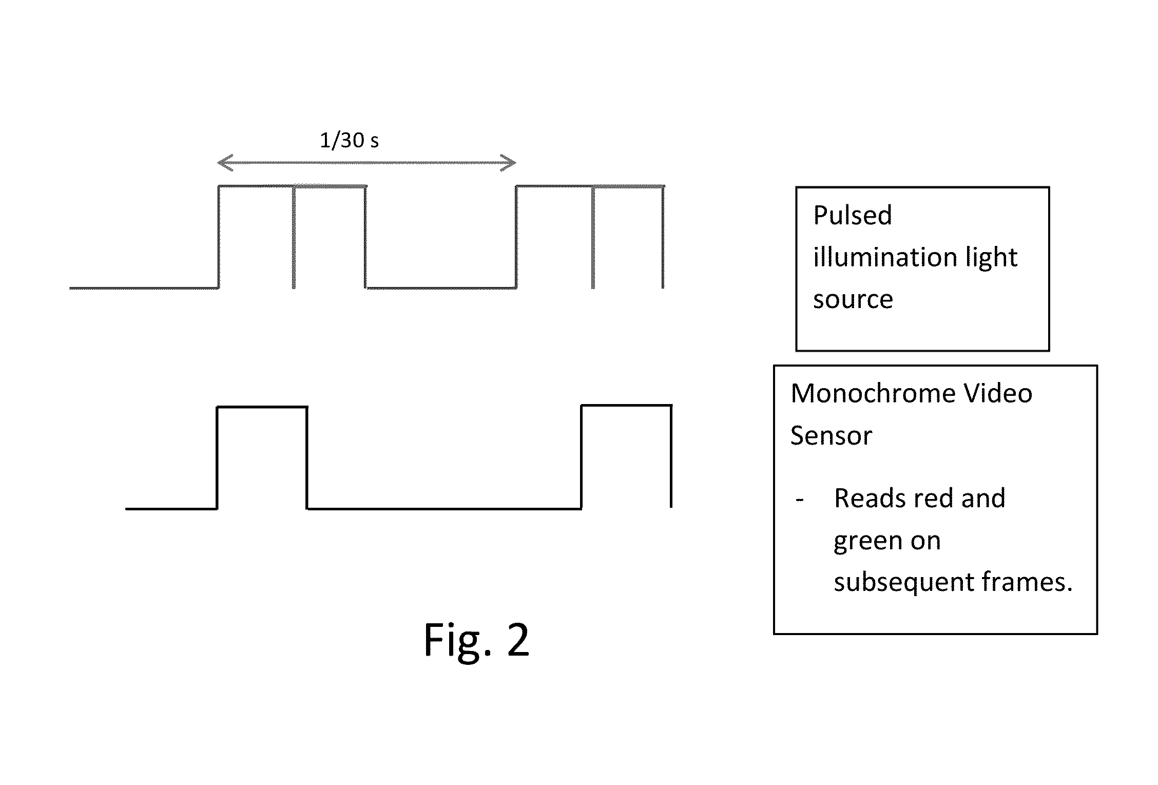
[0019]FIG. 1 is a diagram illustrating pulsed illumination and capture of image signals in a sensor to enable decoding of signals from chrominance channels. In this example, pulsed red and green colored illumination is synchronized with a video color sensor. This allows red and green color planes to be read out from the video color sensor.

[0020]When a package is moved past the capture device, it has low motion blur since a short illumination exposure time is used. The red frame and green frame are synchronized in time, so a signal encoded in chrominance can be detected by subtracting the two color planes. See U.S. Pat. No. 8,199,969, and US Patent Application Publication 20100150434, incorporated above. See also, US Patent Application Publications 20110212717 and 20130195273, and application Ser. No. 13 / 888,939 by John Lord et al., describing various arrangements for capturing images under different illumination and combining the images to enhance signal detection and recognition, i...


PUM


Abstract

Signal detection and recognition employees coordinated illumination and capture of images under to facilitate extraction of a signal of interest. Pulsed illumination of different colors facilitates extraction of signals from color channels, as well as improved signal to noise ratio by combining signals of different color channels. The successive pulsing of different color illumination appears white to the user, yet facilitates signal detection, even for lower cost monochrome sensors, as in barcode scanning and other automatic identification equipment.

Description

RELATED APPLICATION DATA[0001]This application is a continuation in part of U.S. patent application Ser. No. 13 / 011,618, filed Jan. 21, 2011 (published as US Patent Application Publication 20110212717), which is a continuation of PCT application PCT / US09 / 54358, filed Aug. 19, 2009 (published as WO2010022185). Application PCT / US09 / 54358 claims priority benefit to 61 / 226,195, filed 16 Jul. 2009. This application is also a continuation in part of U.S. patent application Ser. No. 13 / 888,939, filed May 7, 2013, which is a continuation-in-part of co-pending application Ser. No. 13 / 745,270, filed Jan. 18, 2013 (published as US Patent Publication 20130195273). These applications are hereby incorporated by reference.TECHNICAL FIELD[0002]The invention relates to image signal capture and processing, as this processing is used in conjunction with associated image-based signal encoding and decoding, image recognition and object recognition.BACKGROUND AND SUMMARY[0003]Conventional barcode scanner...

Claims


Application Information

Patent Timeline
IPC IPC(8): H04N9/73G06V10/141G06V10/143G06V10/147
CPCH04N9/73H04N1/482H04N1/40056G06K7/12G06F16/9554H04N1/484G06V10/141G06V10/143G06V10/147H04N23/56G06K7/10722G06K7/1413H04N5/33
Inventor BOLES, JACOB L.REED, ALASTAIR M.LORD, JOHN D.
Owner DIGIMARC CORP
Why Eureka
Try Eureka