
Tinted polycarbonate ophthalmic lens product and method of manufacture

Active Publication Date: 2013-12-12
YOUNGER MFG
View PDF4 Cites 46 Cited by
  • Summary
  • Abstract
  • Description
  • Claims
  • Application Information

AI Technical Summary

Benefits of technology

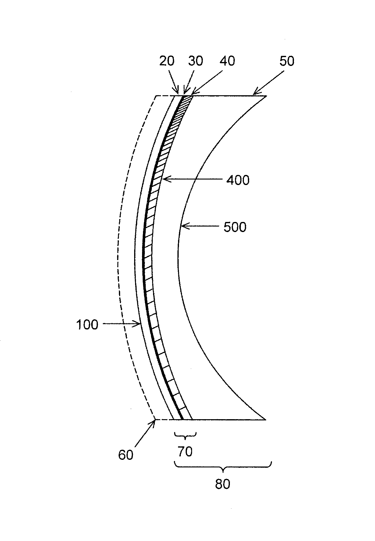
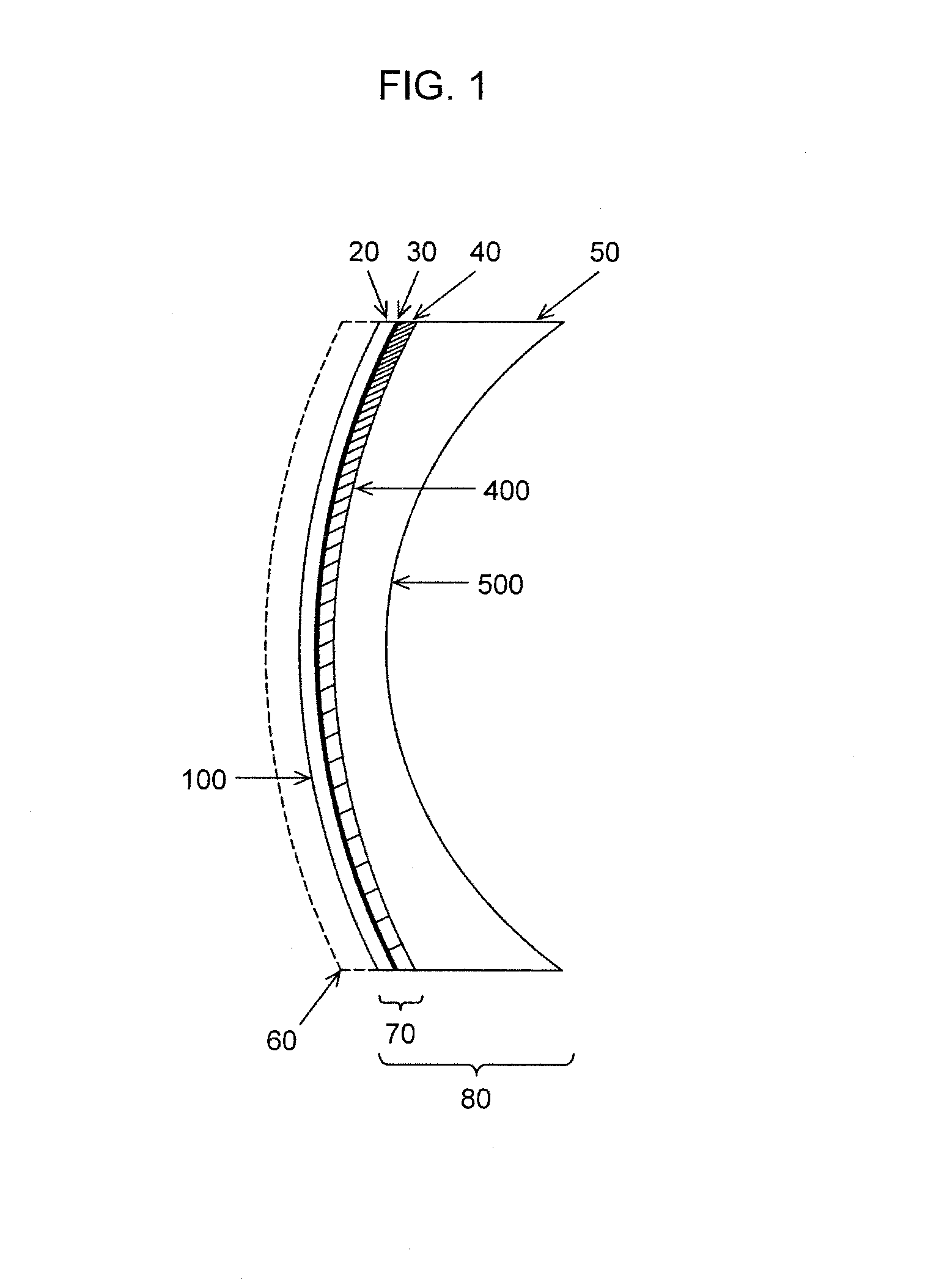
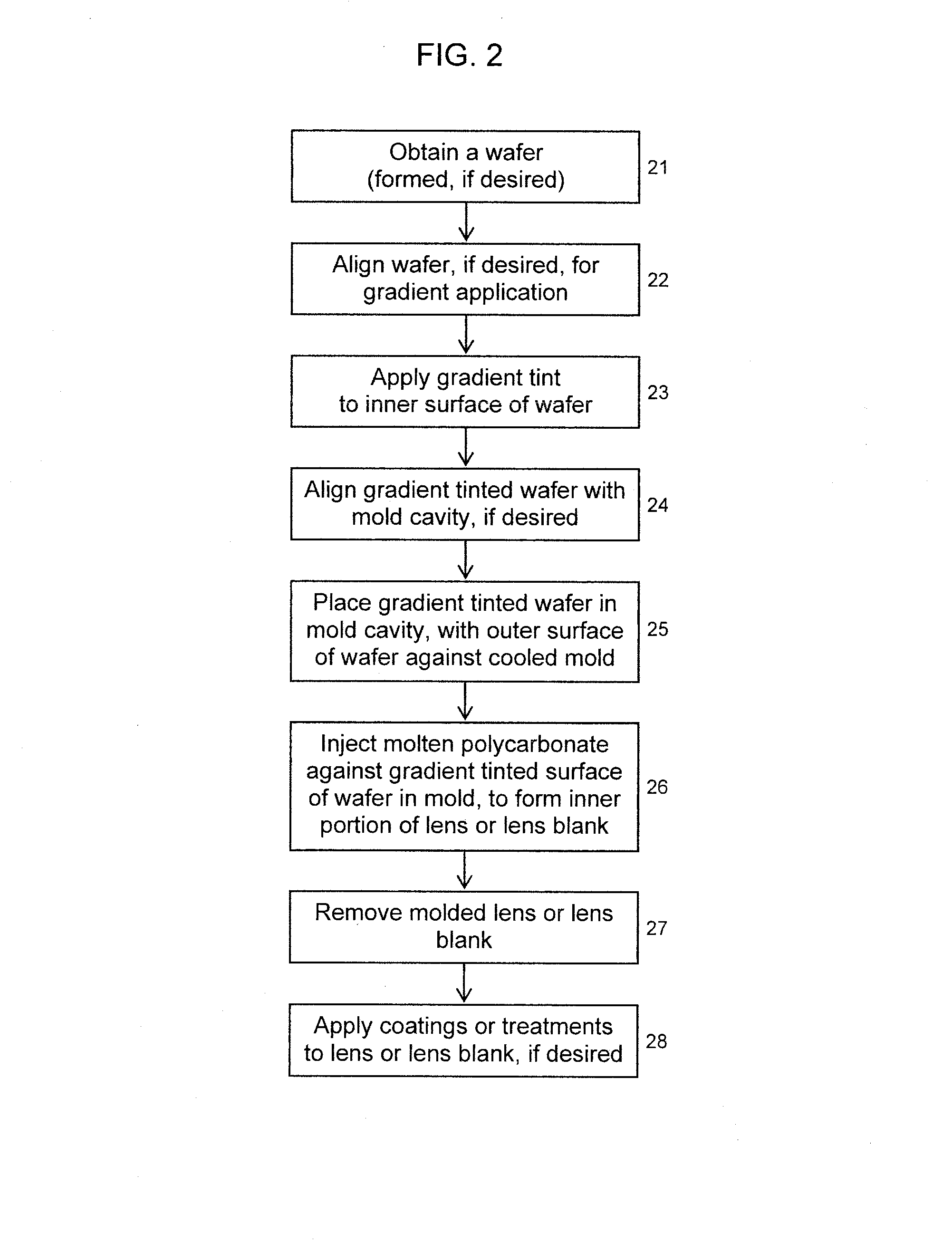
This patent provides a method for making ophthalmic lenses or blanks with a tinted or gradient-tinted inner layer. The method involves tinting the inner polymeric layer of a multilayer wafer, placing the outer layer against a cooled mold, and injecting molten polycarbonate against the inner tinted surface to form the lens portion closest to the eye. The resulting lens or blank has improved optical performance and is suitable for use as eyewear. The patent also describes the use of specific coatings and additives to enhance the lens's properties.

Problems solved by technology

Unfortunately, many thermoplastic polymers, and particularly the popular polycarbonate lens material, absorb dyes from solution very poorly.
Many common organic solvents dissolve, discolor or structurally weaken polycarbonate and therefore may not offer viable alternative routes to introduce dyes.
While additives may allow sufficient absorption of the dye into the polycarbonate to provide the desired color or attenuation initially, the dyes may be unstable to continued light exposure and may fade or migrate with time.
Over-saturation of material tinting may allow sufficient color to remain in the final lens, but solution of the excess dye can unacceptably contaminate the coating process.
Adding dye to the stock resin for polycarbonate injection-molding does not allow the manufacturing freedom to create a variety of differently colored products.
It can be expensive and time-consuming to purge colored material from the injection molding machinery prior to running other colors or clear material.
In addition, and importantly, many dyes cannot withstand the high temperature and pressure of polycarbonate injection molding.
Other dyes will not dissolve or disperse evenly within polycarbonate and therefore this approach is of limited application.
In addition, if one wants a gradient tint across the surface of the molded lens, it cannot be easily accomplished with dyed resin.
One significant problem with this approach is that the heat of the injection molding process may severely degrade the dyes.
Burning or severe fading of the dyes in the gate areas where molten polycarbonate is first introduced is especially problematic.
This problem is more severe with polycarbonate than with many other thermoplastic materials, due to the higher temperatures required for polycarbonate molding.
Another common problem is poor adhesion between the wafer or insert and the polycarbonate used for injection due to physical or chemical differences between these materials.
For multilayer wafers, the necessary steps of lamination and / or treatment(s) for improved adhesion of these multilayer structures may create additional stresses within the wafer that reduce compatibility with the injected material.
However, extra layers increase the overall complexity and thickness of the final product, which may not be acceptable for eyeglass lenses.
This additional complexity and cost is likewise pointed out in U.S. Pat. No. 6,117,384, which recommends using a single layer substrate due to the impracticality of multiple layers.
Such a configuration is not practical for prescription lenses because prescription lenses require thickness differences across the lens to create the vision correction lensing effect.

Method used


Image

  • Tinted polycarbonate ophthalmic lens product and method of manufacture
  • Tinted polycarbonate ophthalmic lens product and method of manufacture
  • Tinted polycarbonate ophthalmic lens product and method of manufacture

Examples


example 1

[0089]Round, 76 mm diameter linearly polarized gray polycarbonate wafers (product code YNG, Wintec International Japan, Inc.) for use in eyewear lens products were obtained with a nominal 6B spherical radius of curvature (the typical range of radii for these wafers is 84.8 mm to 86.8 mm). The construction of the original wafer layers and their removable sheets was as follows, starting from the outer surface:

[0090]static-held protective sheet / / polycarbonate layer / polarizer

[0091]layer / polycarbonate layer / / static-held protective sheet.

The polycarbonate layers are adhesively joined to the polarizing layer in this wafer.

[0092]Both protective sheets on each wafer were removed. The wafers were mounted in the lens holder, immersed in the Lens Prep II solution for two minutes, and then dipped for gradient tinting using the four-cycle process described previously.

[0093]Visual inspection showed dye present on both sides of the wafers and a gradient tint pattern. The portion of each wafer that ...

example 2

[0095]A 6B wafer was prepared in the same manner as EXAMPLE 1, except the cleaning in the Lens Prep II solution was reduced to one minute in the 190-200° F. (87.8-93.3° C.) bath.

[0096]Visual inspection showed dye present on both sides of the wafer, and a gradient tint pattern. Significantly less crazing and micro-cracking of the surfaces was observed than for EXAMPLE 1.

example 3

[0097]6B wafers were prepared as in EXAMPLE 2 with gradient tints on both the inner and outer surfaces of the wafer. The wafers were dried in air at 80° C. for one hour prior to molding.

[0098]A gradient-tinted wafer was placed against the outer, actively cooled surface of a mold cavity in an Engel (Engel Austria GmbH) 300-ton vertical injection-molding machine. Sabic (Saudi Basic Industries Corporation) OQ3820-1111 optical grade polycarbonate was injected at normal molding conditions against the inner surface of the wafer to fill the mold cavity designed to produce an eyewear 6B single vision semi-finished lens blank.

[0099]The eyewear lens blank was removed from the mold cavity and inspected. The outer surface of the lens (which was also the outer surface of the wafer) showed excessive haze, crazing and micro-cracking. Upon moderate rubbing with a dry cloth, the tint could be partially wiped off the outer surface. Visual inspection of the lens blank showed that a gradient tint had b...


PUM


Abstract

The present invention describes ophthalmic lens products comprising a multilayer wafer and an injection-molded polycarbonate inner portion. The multilayer wafer includes a dyed, photochromic or polarized layer between a tinted inner layer and an outer polymeric layer. The inner layer may be solid or gradient-tinted. The polycarbonate inner portion of the lens product is directly fused to the tinted inner layer of the multilayer wafer during injection molding. The invention further describes a method to produce a gradient-tinted polarized polycarbonate eyewear lens product by obtaining a multilayer wafer having an outer layer, an inner polycarbonate layer, and a polarized layer between the inner and outer layers, applying a gradient tint to the wafer's inner layer, placing the gradient tinted wafer within an injection-molding cavity, and injecting molten polycarbonate directly against the wafer's gradient-tinted layer to form the inner portion of the lens product and to fuse it to the wafer.

Description

CROSS-REFERENCE TO RELATED APPLICATION[0001]Not applicable.FEDERALLY SPONSORED RESEARCH OR DEVELOPMENT[0002]Not applicable.JOINT RESEARCH AGREEMENT[0003]Not applicable.SEQUENCE LISTING[0004]Not applicable.BACKGROUND OF THE INVENTION[0005]1. Field of the Invention[0006]The field of the invention relates generally to ophthalmic lens products and more specifically to lenses and lens blanks for eyewear, the lenses preferably having a gradient tint that varies across the lens.[0007]2. Description of the Related Art[0008]Ophthalmic lenses are commonly used to correct vision errors, aberrations and focusing deficiencies caused by age, disease or other factors. In addition to correcting physiological vision problems, ophthalmic lenses and eyewear may also be used to ameliorate physical or environmental conditions (such as glare, variable lighting, high intensity light, dust, condensation, etc.) that can affect sight. Eyewear may also incorporate aesthetic features for fashion and style.[000...

Claims


Application Information

Patent Timeline
IPC IPC(8): G02C7/10G02B1/08G02C7/12
CPCB29D11/00009B29D11/00644B29D11/00653B29D11/0073G02C7/102G02C7/105G02C7/12
Inventor BARZAK, ADAM AHMADMCKENZIE, ANDREW JOHNAMBLER, DAVID MARK
Owner YOUNGER MFG
Learn More