Metallic Wick

a technology of wick and wick body, which is applied in the field of wick, can solve the problems of inconvenient and wasteful, users can only replenish fuel or replace a new wick, and the wick is difficult to be inserted through the disk, so as to reduce manufacturing costs and draw more viscous fuel. the effect of speed

Active Publication Date: 2013-12-12
PRO IRODA INDS
View PDF13 Cites 8 Cited by
  • Summary
  • Abstract
  • Description
  • Claims
  • Application Information

AI Technical Summary

Benefits of technology

[0018]An advantage of the metallic wick according to the present invention is that the metallic wick cannot be carbonized or consumed to maintain a fixed height thereof to maintain the flame combustion scale.
[0019]Another advantage of the metallic wick according to the present invention is that the metallic wick includes an end producing the flame thereon and heated by the flame to cause fuel drawn to the end thereof vaporized and combusted more completely due to higher wick temperature.
[0020]A further advantage of the metallic wick according to the present invention is that the number of circles, the size of meshes, the surface roughness and the coating materials of the mesh member are adjustable to control ability of capillary action adapted for wicking various fuels with different viscosity, so that the metallic wick can draw more viscous fuel faster to the tip thereof and can be ignited shortly (one minute or less) after inserting the wick in fuel.
[0021]A further advantage of the metallic wick according to the present invention is that the metallic wick does not loosen at its terminal end after cutting a predetermined length or trimming to be mounted to a lamp device easily.
[0022]A further advantage of the metallic wick according to the present invention is that the metallic wick is made of metal reducing manufacturing costs to provide a popular price, in a preferred form, the metallic wick can be formed by a common metal wire mesh.

Problems solved by technology

However, after trimming, the cotton wick is easily loosened at its terminal end to cause it difficultly being inserted through the disk.
Trimming the cotton wick results in the wick eventually unconnected with fuel, so that users can only replenish fuel or replace a new wick.
It is inconvenient and wasteful.
However, cotton wicks with low stiffness and fire-resistance cannot be adjusted easily to maintain proper fuel wicking and flame scale, especially for high viscosity or high flash point fuels results in producing carbon deposits and difficult to ignite.
If the fuel drawn is slower than it burns, wick will be carbonized and burnt out.
If the fuel drawn is more than it burns, usually occurring on burning high flash point fuel, will cause slow evaporation of the fuel and produce soot due to incomplete combustion.
Incomplete combustion not only produces soot but also toxic fumes.
The fiberglass layer is able to draw fuel by capillary action, hard to burn down, and not easily being loosened at its terminal end.
However, the fiberglass layer does not draw fuel effectively causing the flame extinguishes easily and the flame scale is difficult to be controlled.
Therefore, the wick disclosed by said patents both include fiberglass filaments, but the fiberglass is expansive, difficult processing.
Momentously, the wick is a large quantity of consumable items, but the fiberglass wick is expensive, and not environment-friendly.
Additionally, when the fiberglass wick is processed, inhaling the fiberglass can cause damage to human lungs and be harmful to manufacturing personnel.
Inhaling of fiberglass will jeopardize the health of workers during fiberglass-reinforced plastic processing.
The fiberglass fiber can also cause skin, eye and throat irritation to users.
At higher exposure levels, the fiberglass also has been associated with skin rashes and difficulty in breathing.
Thus, the user cannot adjust the flame height or scale easily.
At the same time, the user may also contact fuel in the wick and cause inconvenience or even danger.

Method used


Image

  • Metallic Wick
  • Metallic Wick
  • Metallic Wick

Examples


Embodiment Construction

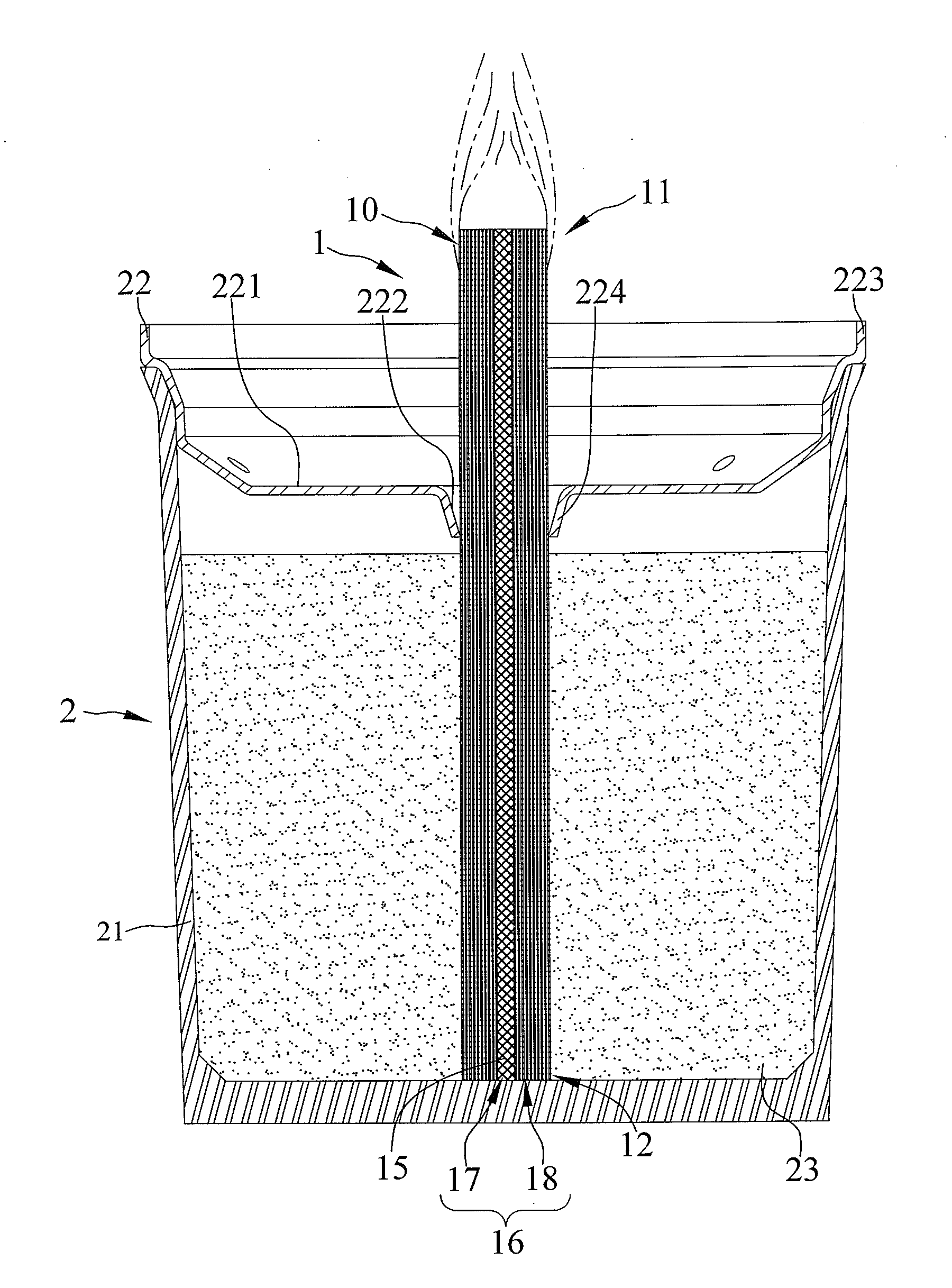
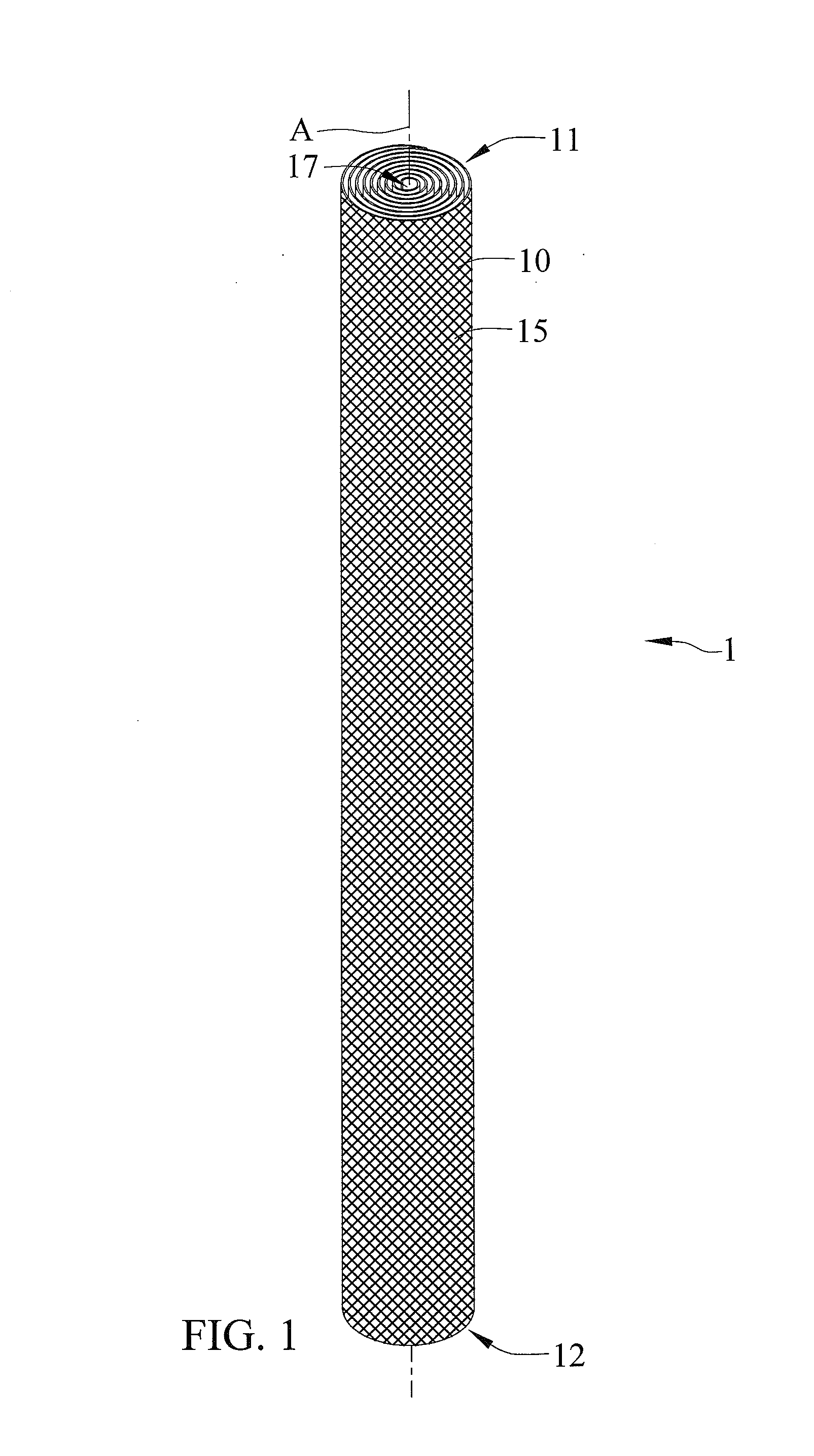
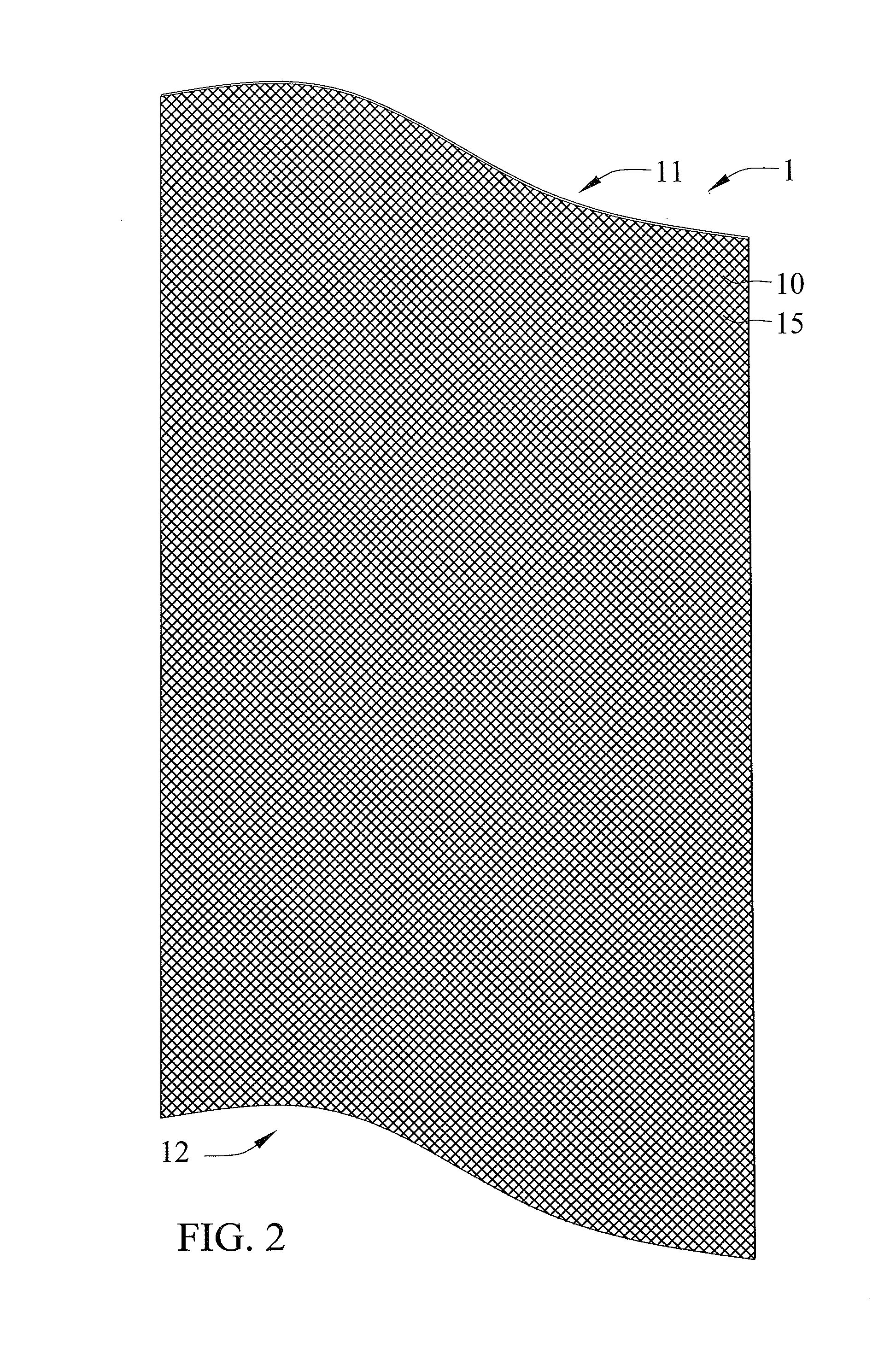
[0047]FIGS. 1 through 3 show a first embodiment of a metallic wick according to the present invention shown in the drawings. The metallic wick 1 generally includes a mesh member 10 made of metal and rolled into a tubular shape and having a plurality of circles spaced from each other along a longitudinal axis A to form an Archimedean spiral cross-section perpendicular to the longitudinal axis A. The mesh member 10 includes first and second ends 11 and 12 disposed opposite to each other along the longitudinal axis A, and first and second surfaces 13 and 14 respectively extended from the first end 11 to the second end 12 thereof and arranged opposite to each other. Furthermore, the mesh member 10 essentially includes a plurality of metallic wires interlacing and overlapping each other to form into a plurality of meshes 15 penetrating the first and second surfaces 13 and 14 between the first and second ends 11 and 12 thereof. Each of the plurality of meshes 15 is formed in a quadrilater...


PUM


Abstract

A metallic wick includes at least one mesh member having first and second ends disposed opposite to each other, first and second surfaces respectively extended from the first end to the second end thereof and arranged opposite to each other, a plurality of meshes penetrating the first and second surfaces between the first and second ends thereof, and a transport channel extending from the first end to the second end thereof drawing fuel by capillary action.

Description

BACKGROUND OF THE INVENTION[0001]1. Field of the Invention[0002]The present invention relates to a wick and, more particularly, to a wick made of metal and provided for being mounted to a lamp device for quickly igniting fuel.[0003]2. Description of the Related Art[0004]A conventional lamp device includes a fuel cup storing fuel, a high temperature resistant disk mounted on the fuel cup, and a wick inserted through the disk to connect with fuel stored in the fuel cup. Moreover, the wick is normally made out of braided cotton and works by capillary action. Fuel is drawn up through the wick to reach the flame produced on the disk. The above lamp device is actively used for various purposes, such as lighting, decorating, or increasing atmosphere. For example, an oil lamp is used in religion, or an alcohol lamp is used in medical or chemical laboratories.[0005]The conventional cotton wick must be cut to a predetermined length adapted for being mounted to the lamp device. However, after ...

Claims


Application Information

Patent Timeline
Patent Type & Authority Applications(United States)
IPC IPC(8): F23D3/08F23D3/18
CPCF23D3/08F23D3/18C11C5/006F21S13/12F21V37/0008F21V37/002
Inventor CHEN, WEI-LONG
Owner PRO IRODA INDS
Why Eureka
Try Eureka