Cold cathode fluorescent discharge lamp apparatus and operating method for same

a fluorescent discharge lamp and cold cathode technology, which is applied in the direction of instruments, light sources, inductances, etc., can solve the problems of increased reactive power during the operation of the discharge lamp, increased luminance, and leakage current from the discharge lamp, so as to achieve effective smooth operation, and suppression of leakage current

Inactive Publication Date: 2008-01-01
SONY CORP
View PDF7 Cites 4 Cited by
  • Summary
  • Abstract
  • Description
  • Claims
  • Application Information

AI Technical Summary

Benefits of technology

[0015]Therefore, in the above-described configurations according to the embodiments of the invention, an AC voltage with a first frequency for operation of a discharge lamp is applied when the operation of the discharge lamp is started (the discharge lamp is ignited). Subsequently, after the ignition of the discharge lamp, an AC voltage with a second frequency lower than the first frequency is applied so that the operation of the discharge lamp is continued. That is, the frequency of the AC voltage is switched so that an AC voltage with a relatively high frequency is used to ignite the discharge lamp while an AC voltage with a low frequency is used to operate the discharge lamp after the ignition. Thus, the discharge lamp can be ignited smoothly with a low discharge start voltage in a short time period as the ignition time period of the discharge lamp. In addition, during continuation of the operation of the discharge lamp, the amount of leakage current is suppressed.
[0016]As described above, embodiments of the invention allow effective suppression of leakage current during operation of a discharge lamp without deteriorating the start performance of the discharge lamp. Thus, the embodiments allow e.g. enhancement of the luminance of the discharge lamp and an improvement of the power conversion efficiency due to reduction of reactive power.

Problems solved by technology

It is known that when a discharge lamp is operated through AC driving, leakage current from the discharge lamp arises.
This current reduction possibly causes e.g. a decrease in the luminance and an increase in reactive power during the operation of the discharge lamp.

Method used


Image

  • Cold cathode fluorescent discharge lamp apparatus and operating method for same
  • Cold cathode fluorescent discharge lamp apparatus and operating method for same
  • Cold cathode fluorescent discharge lamp apparatus and operating method for same

Examples


Embodiment Construction

[0022]Prior to a description of a best mode (embodiment) for carrying out the present invention, a background to the achievement of the invention will be described below with reference to FIGS. 4 and 5.

[0023]FIG. 4 illustrates a discharge lamp 1 that is a cold cathode fluorescent lamp. The discharge lamp 1 includes a sealed container 2 formed by processing an insulating material with optical transparency such as glass into a hollow pillar shape. The inside of the sealed container 2 is a substantially vacuum closed space, and e.g. a mercury gas is enclosed therein as a gas for luminescence. The inner surface of the sealed container 2 is coated with a fluorescent material.

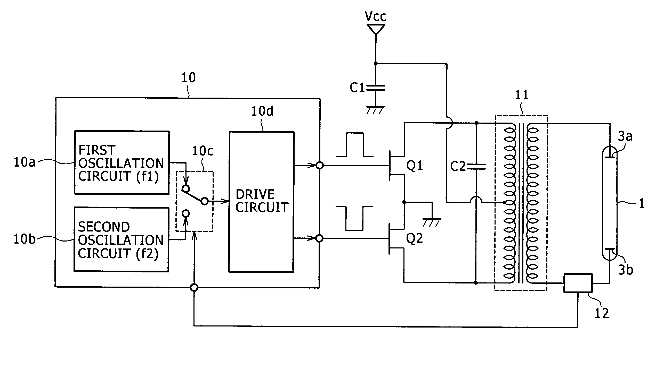
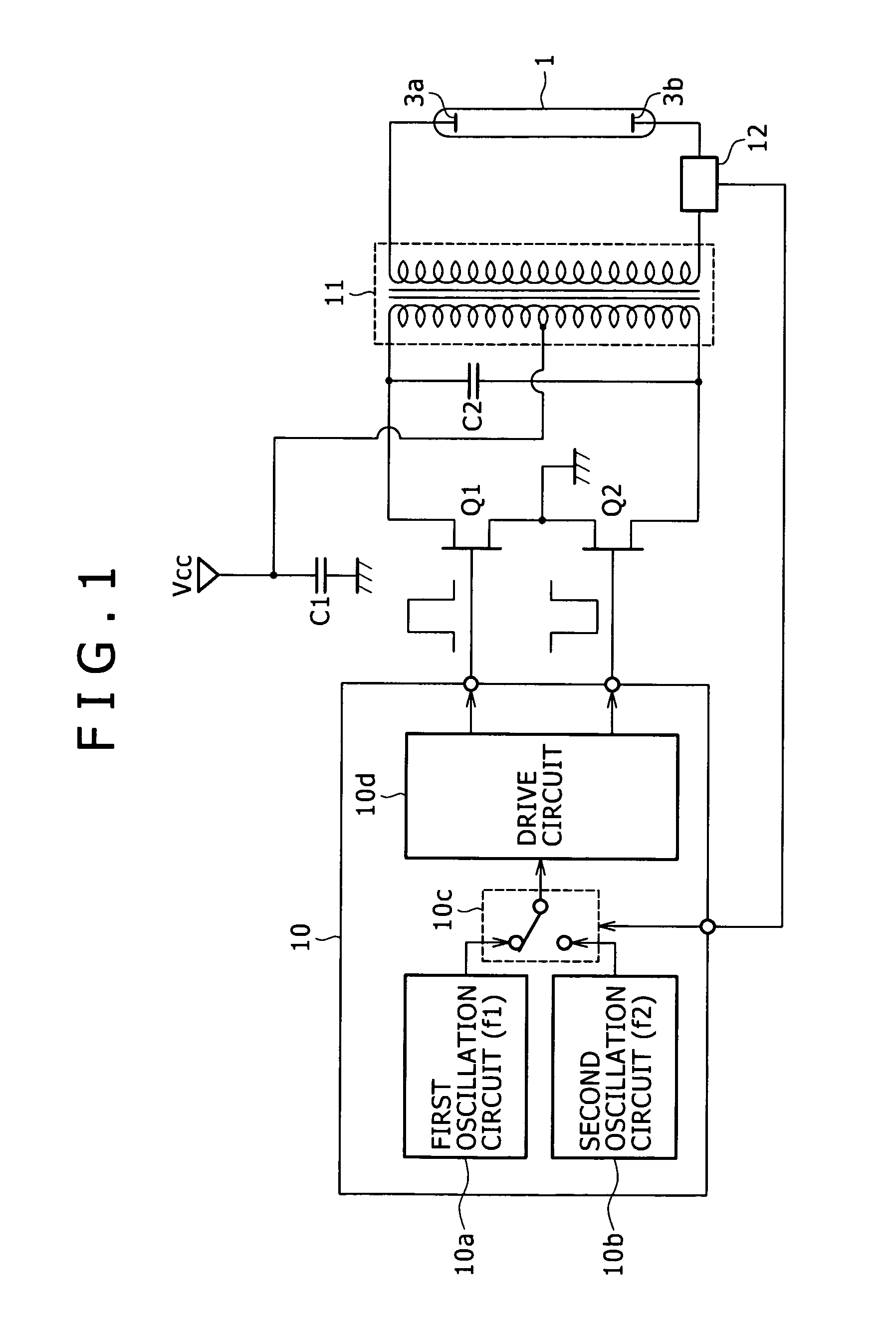
[0024]Electrodes 3a and 3b are provided at the both ends of the longitudinal axis of the space inside the pillar-shaped sealed container 2. These electrodes 3a and 3b are routed to the external of the sealed container 2 through a conductive material so as to be coupled to e.g. a lamp drive circuit to be described lat...


PUM


Abstract

A discharge lamp operating device includes a voltage application unit that applies to a discharge lamp an alternating-current (AC) voltage for operation of the discharge lamp, and a frequency setting unit that sets a frequency of the AC voltage to a first frequency for ignition of the discharge lamp and sets the frequency of the AC voltage to a second frequency during operation of the discharge lamp after the ignition. In the discharge lamp operating device, the second frequency is lower than the first frequency.

Description

CROSS-REFERENCE TO RELATED APPLICATIONS[0001]The present application claims priority from Japanese Patent Application No. JP 2005-218672 filed on Jul. 28, 2005, the disclosure of which is hereby incorporated by reference herein.BACKGROUND OF THE INVENTION[0002]1. Field of the Invention[0003]The present invention relates to a device and a method for operating a discharge lamp. The invention also relates to a light source device and a display that include the discharge lamp operating device.[0004]2. Description of the Related Art[0005]Liquid crystal displays that employ a liquid crystal panel as a display unit are widely prevalent. As is well known, the liquid crystal panels are not self-luminous devices. Therefore, the liquid crystal panels allow the passage therethrough of light emitted from a light source device referred to as a so-called backlight, and modulate the passing light based on video signals to thereby display images.[0006]Currently, discharge lamps such as cold cathode ...

Claims


Application Information

Patent Timeline
Patent Type & Authority Patents(United States)
IPC IPC(8): G05F1/00
CPCH05B41/2828H05B41/24H01F38/08H05B41/02H05B41/26
Inventor USAMI, YOSHIHIKOFURUKAWA, NORIMASA
Owner SONY CORP
Why Eureka
Try Eureka