Wood chipper, control system therefor, and method thereof

a control system and chipper technology, applied in the field of wood and brush chippers, can solve the problems of one or more systems and components of the chipper, operation downtime and/or damage, and the winch line may become entangled in the feed wheel assembly, so as to prevent the operation of the cutting system

Active Publication Date: 2013-12-19
BANDIT IND
View PDF2 Cites 7 Cited by
  • Summary
  • Abstract
  • Description
  • Claims
  • Application Information

AI Technical Summary

Benefits of technology

[0010]The aforementioned drawbacks and disadvantages of these former wood chippers have been identified and a solution is set forth herein by the inventive wood chipper which includes a frame; an infeed system; a cutting system spaced from the infeed system; at least one feed wheel disposed between the infeed system and the cutting system to feed wood material to the cutting system; a winch operatively attached to the frame; a winch line operatively attached to the winch and comprising a first end; and a detector adapted to detect a first and a second position of the winch line, wherein the detector is adapted to allow operation of the at least one feed wheel and prohibit operation of the winch when the first position of the winch line is detected, and to allow operation of the winch and allow operation of the at least one feed wheel in a predefined manner when the second position is detected. This embodiment may further include, wherein: the predefined manner comprises preventing the operation of the at least one feed wheel and may further include preventing the operation of the cutting system; the predefined manner comprises operating the at least one feed wheel in a reverse direction, and may further include preventing the operation of the cutting system; the detector is disposed adjacent an operational path of the winch line; the detector is disposed adjacent an end of a boom, the boom enclosing a portion of the winch line; the winch line is enclosed when in the first position; a portion of the winch line from a proximate end to a distal end is enclosed when in the first position; the detector is disposed forwardly of an infeed chute; a probe disposed adjacent the first end of the winch line; the detector operatively disposed adjacent the winch line in order to detect the probe, and may further include when the probe and detector are adjacent, the winch line is in the first position, and when the probe and the detector are not adjacent, the winch line is in the second position, or the winch line comprises an end loop disposed adjacent the first end and the probe is disposed rearwardly of the end loop; the detector is a sensor adapted to sense when the winch line is in the first and second position, and further the sensor is a positional sensor adapted to sense the position of the winch line, and yet further, a band disposed adjacent the first end of the winch line, the band adapted to define the first and second position of the winch line, or the sensor is operatively disposed adjacent the winch line in order to sense the band, and further the sensor is operatively disposed adjacent the winch line in order to detect the band; wherein when the band and detector are adjacent, the winch line is in the first position, and when the probe and the detector are not adjacent, the winch line is in the second position; a collar disposed adjacent the first end of the winch line; and wherein the detector is a switch comprising a first and a second position, the first position allowing operation of the at least one feed wheel and prohibiting operation of the winch, the second position allowing operation of the winch and allowing operation of the at least one feed wheel in the predefined manner, the switch operatively attached to the frame such that the collar is adapted to move the switch to the first position when the winch line is in a retracted position and releases the switch to the second position when the winch line moved from the retracted position, and further the switch is a momentary switch normally biased to the second position, and yet further, the collar is positionable along the winch line. Still further yet, the sensor may comprise a magnetic pick-up, the detector may be disposed adjacent an operational path of the winch line, the detector may be disposed forwardly of the housing, the winch line may be substantially enclosed within an extended housing when in a stored position, and the winch line may comprise and end loop and the probe is disposed aft of the end loop. Still further, alternate embodiments may comprise a boom for enclosing the winch line in an operational configuration, the boom extending from the winch, the boom comprising a guide portion disposed at a distal end thereof, and-the switch is disposed on the distal end of the boom, and yet further wherein the infeed assembly comprises an infeed chute and the boom is disposed on the infeed chute, and yet further, a distal end of the boom extends over an infeed tray.

Problems solved by technology

Although these existing types of chippers have worked well, they suffer from the disadvantage that, inter alia, the winch line may become entangled in the feed wheel assembly if the winch line is extended while the feed wheel assembly is operating.
As a result of this, the extended winch line can unintentionally be fed into the feed wheel assembly, and further may be fed into or captured by the cutting assembly thereby causing operational downtime and / or damage to one or more systems and components of the chipper.

Method used


Image

  • Wood chipper, control system therefor, and method thereof
  • Wood chipper, control system therefor, and method thereof
  • Wood chipper, control system therefor, and method thereof

Examples


Embodiment Construction

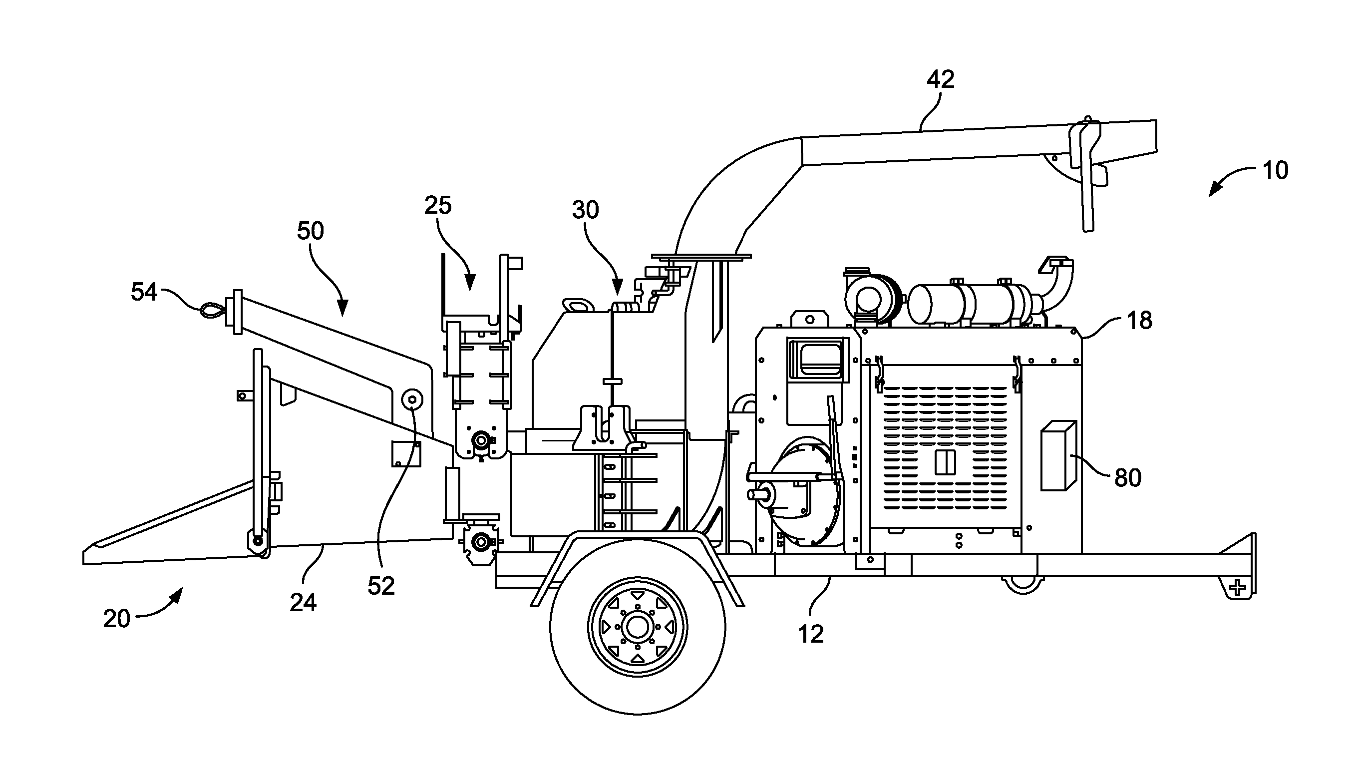
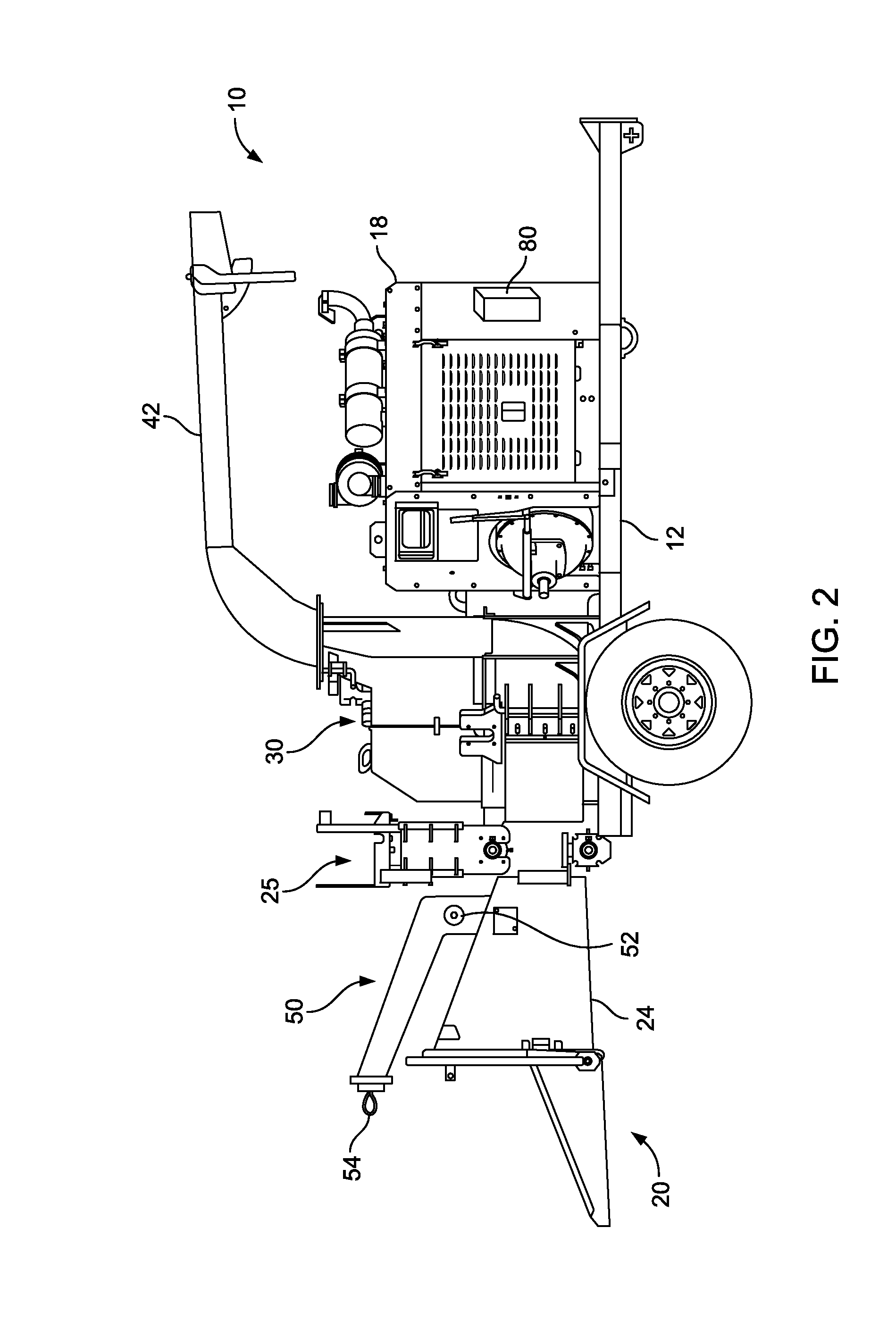
[0086]The best mode for carrying out the invention is presented in terms of the preferred embodiment, wherein similar referenced characters designate corresponding features throughout the several figures of the drawings.

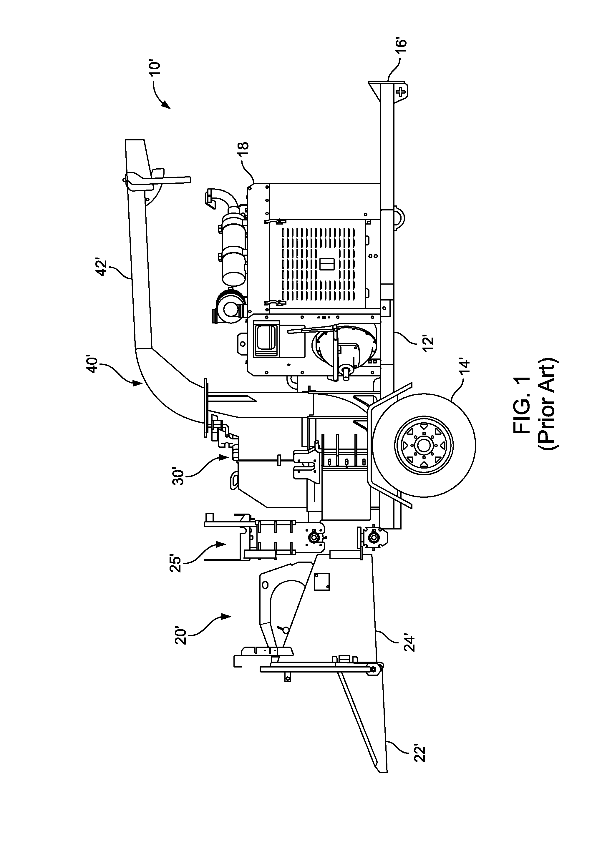
[0087]For purposes of description herein, the terms “upper”, “lower”, “right”, “left”, “rear”, “front”, “vertical”, “horizontal”, and derivatives thereof, shall relate to the invention as oriented in FIG. 1. However, it is to be understood that the invention may assume various alternative orientations, except where expressly specified to the contrary. It is also to be understood that the specific devices and processes illustrated in the attached drawings and described in the following specification are exemplary embodiments of the inventive concepts defined in the appended claims. Hence, specific dimensions and other physical characteristics relating to the embodiments disclosed herein are not to be considered as limiting, unless the claims expressly state otherwise....


PUM

PropertyMeasurementUnit
timeaaaaaaaaaa
pressureaaaaaaaaaa
timeaaaaaaaaaa

Abstract

A wood chipper comprises a frame, an infeed system, a rotatable cutting system, and at least one feed wheel disposed between the infeed system and the cutting system to feed wood material to the cutting system. The wood chipper also includes a winch comprising a winch line having a first end, and a collar disposed adjacent the first end of the winch line. The wood chipper further includes a detector adapted to detect a first and a second position of the winch line, wherein the detector is adapted to allow operation of the at least one feed wheel and prohibit operation of the winch when the first position of the winch line is detected, and to allow operation of the winch and allow operation of the at least one feed wheel in a predefined manner when the second position is detected. The wood chipper further comprises a bypass for operation of the at least one feed wheel.

Description

CROSS REFERENCE TO RELATED APPLICATIONS[0001]This application is a continuation-in-part of co-pending U.S. patent application Ser. No. 13 / 433,962, entitled “Wood Chipper, Control System Therefor, and Method Thereof” which was filed Mar. 29, 2012, which claims the benefit of the filing date of U.S. provisional application Ser. No. 61 / 468,680, entitled “Wood Chipper, Control System Therefor, and Method Thereof” which was filed on Mar. 29, 2011, the complete subject matter each of which are hereby incorporated herein by reference, in their entirety. This application is also a continuation-in-part of co-pending U.S. patent application Ser. No. 13 / 434,221, entitled “Wood Chipper, Control System Therefor, and Method Thereof” which was filed Mar. 29, 2012, which claims the benefit of the filing date of U.S. provisional application Ser. No. 61 / 468,680, entitled “Wood Chipper, Control System Therefor, and Method Thereof” which was filed on Mar. 29, 2011, the complete subject matter each of w...

Claims


Application Information

Patent Timeline
Patent Type & Authority Applications(United States)
IPC IPC(8): B27L11/00
CPCB27L11/00B66D1/46B02C23/02B02C18/2225A01G3/002
Inventor MOREY, MICHAEL BOYD
Owner BANDIT IND
Why Eureka
Try Eureka