Injection molding method and injection mold assembly

a technology of injection molding and injection molds, which is applied in the direction of lamination, chemistry apparatus and processes, applications, etc., can solve the problems of insufficient bonding strength, inability to exhibit original adhesion, and decrease in the bonding strength between the surface of the molded article and the transfer layer, so as to reduce the deterioration of printed designs, and reduce the effect of deterioration

Inactive Publication Date: 2013-12-19
PANASONIC INTELLECTUAL PROPERTY MANAGEMENT CO LTD
View PDF15 Cites 10 Cited by
  • Summary
  • Abstract
  • Description
  • Claims
  • Application Information

AI Technical Summary

Benefits of technology

[0030]According to the present invention, the transfer layer is easily peeled off from the base layer between desired layers even under molding conditions where the temperature of molten resin injected into the molding space of the injection mold is higher than that of molten resin injected in a typical injection-molding synchronous foil transfer process and the temperature of the cavity forming surface constituting the molding space is higher than that of a cavity forming surface set in the typical injection-molding synchronous foil transfer process. This reduces the deterioration of printed designs such as colors and patterns on the transfer layer, achieving a molded article with less deteriorated designs such as colors and patterns. Even under such molding conditions, sufficient bonding strength can be obtained between the molded article and the transfer layer on the molded article. Therefore, the present invention can achieve an injection-molding synchronous foil transfer process using high-value-added engineering plastics having characteristics such as high strength.

Problems solved by technology

Thus, the transfer layer is partially peeled off with the base layer from the molded article, so that desired designs such as colors and patterns may not be transferred onto the surface (transfer surface) of the molded article.
Hence, disadvantageously, an adhesive constituting the adhesive layer is not hardened and thus cannot exhibit original adhesion.
If the adhesive constituting the adhesive layer cannot exhibit the original adhesion, bonding strength between the surface of the molded article and the transfer layer decreases, leading to insufficient bonding strength.
Moreover, the transfer layer is likely to peel off from the surface of the molded article.

Method used


Image

  • Injection molding method and injection mold assembly
  • Injection molding method and injection mold assembly
  • Injection molding method and injection mold assembly

Examples


first embodiment

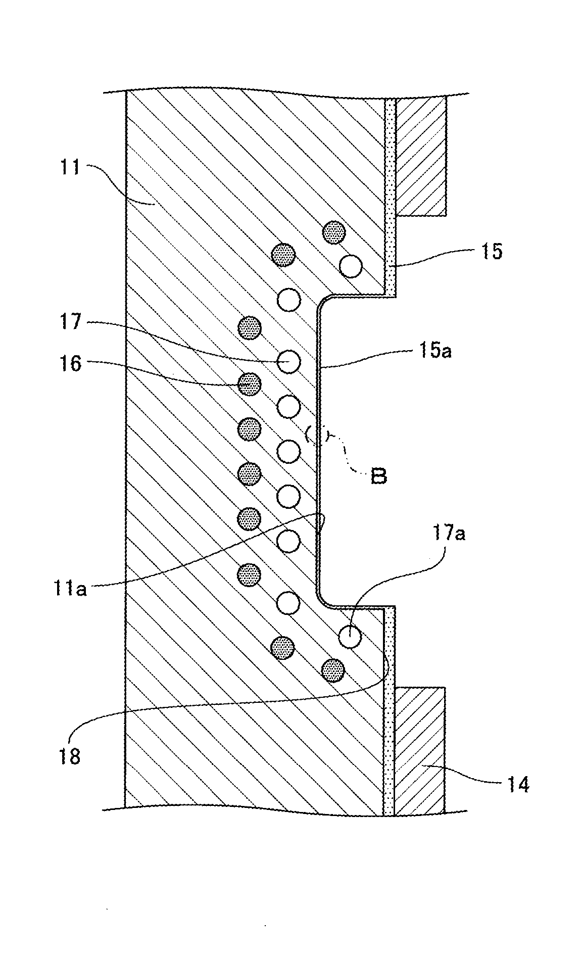
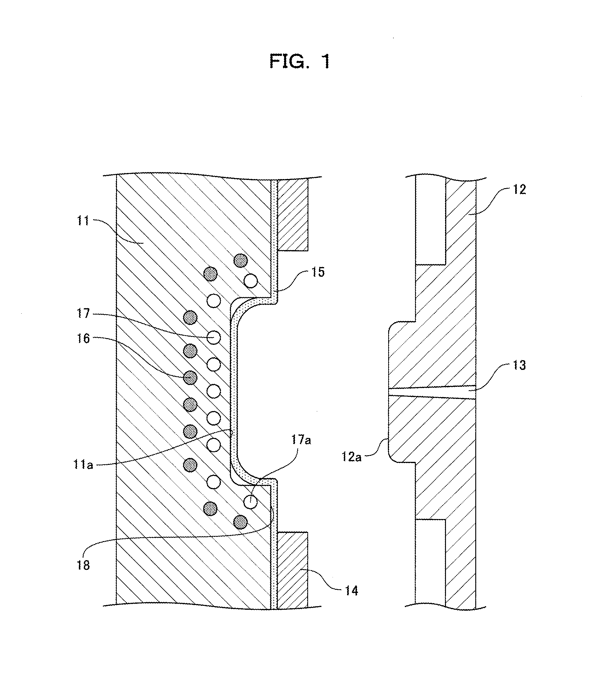
[0046]FIG. 1 is a side cross-sectional view illustrating the main part of a structural example of an injection mold assembly according to a first embodiment. The injection mold assembly performs an injection-molding synchronous foil transfer process. Specifically, in the injection mold assembly, molten resin (engineering plastics) is injected into the molding space (cavity) of an injection mold to obtain a molded article while the transfer layer of a multilayer film disposed in the cavity is transferred onto the surface (transfer surface) of the molded article. The injection mold assembly will be specifically described below.

[0047]As shown in FIG. 1, the injection mold assembly includes a movable mold 11 that is an example of a first mold and a fixed mold 12 that is an example of a second mold. An injection mold is generally made of steel.

[0048]The movable mold 11 has a dented cavity forming surface 11a that is an example of a first cavity forming surface. In the first embodiment, t...

second embodiment

[0076]Referring to FIG. 4, constituent elements different from those described in the first embodiment will be mainly described below according to a second embodiment. FIG. 4 is a plan view schematically showing a structural example of a dented cavity forming surface 11a of a movable mold 11 according to the second embodiment. Parts not illustrated in FIG. 4 are identical to those of the first embodiment and thus the explanation thereof is omitted.

[0077]In the second embodiment, as shown in FIG. 4, the dented cavity forming surface 11a of the movable mold 11 has a rectangular bottom. The bottom has four corners 11b that are curved parts (curved surfaces) with a radius of curvature. Thus, a rounded side connected to the bottom has four straight lines and four corners connecting the four straight lines in plan view. The four corners are the curved parts (curved surfaces).

[0078]In the first embodiment, the temperature of the cooling circuit 17 near the injection mold divided face 18 fo...

third embodiment

[0084]Referring to FIG. 5, constituent elements different from those described in the first embodiment will be mainly described below according to a third embodiment. FIG. 5 is a side cross-sectional view illustrating the main part of a structural example of an injection mold assembly according to the third embodiment. In FIG. 5, the same constituent elements as in FIG. 1 are indicated by the same reference numerals, and the explanation thereof is omitted.

[0085]In the injection mold assembly of the third embodiment, as shown in FIG. 5, a movable mold 11 includes a cooling circuit 20 that is different from the cooling circuit 17 of the first embodiment. The cooling circuit 20 is opposed to the opening end face of a gate portion 13 of a fixed mold 12. For example, in the case where cooling water is passed through the cooling circuit 20, the cooling circuit (water passage) 20 may have a diameter of about 10 mm.

[0086]On a dented cavity forming surface 11a of the movable mold 11, molten ...


PUM

PropertyMeasurementUnit
glass transition temperatureaaaaaaaaaa
surface temperatureaaaaaaaaaa
temperatureaaaaaaaaaa

Abstract

An injection molding method in which a multilayer film including a base layer and a transfer layer stacked on the base layer is disposed in the molding space of an injection mold, the molding space containing the multiplayer film is filled with resin, and then the injection mold is opened to obtain a molded article transferred with the transfer layer peeled from the base layer, wherein after the resin is injected into the molding space, a cooling circuit near the molding space cools the multilayer film before the injection mold is opened.

Description

[0001]The disclosure of Japanese Patent Application No.2012-136473 filed Jun. 18, 2012 including specification, drawings and claims is incorporated herein by reference in its entirety.FIELD OF THE INVENTION[0002]The present invention relates to an injection molding method in which molten resin is injected into the molding space (cavity) of an injection mold to obtain a molded article while the transfer layer of a multilayer film disposed in the cavity is transferred to the surface (transfer surface) of the molded article, and relates to an injection mold assembly for performing the injection molding method.BACKGROUND OF THE INVENTION[0003]In recent years, resin moldings with high-quality appearances, e.g., highly glossy, grained, and weldless moldings have been demanded. To obtain high gloss, a mirror-finished mold surface (cavity forming surface) needs to be transferred with high quality to the surface of injection molding resin. Similarly, to obtain grain, a grained mold surface n...

Claims


Application Information

Patent Timeline
Patent Type & Authority Applications(United States)
IPC IPC(8): B29C45/00
CPCB29C45/0003B29C2045/7343B29C45/73B29C45/14827B29C45/14262B29C45/263B29C2045/1427
Inventor MINE, HIDEONAKANISHI, CHIKARAHIRAISHI, MASAKAZU
Owner PANASONIC INTELLECTUAL PROPERTY MANAGEMENT CO LTD
Why Eureka
Try Eureka