Inner connecting element of a cavity power divider, cavity power divider and manufacturing method thereof

Active Publication Date: 2013-12-19
ANHUI TATFOOK TECH CO LTD
View PDF2 Cites 13 Cited by
  • Summary
  • Abstract
  • Description
  • Claims
  • Application Information

AI Technical Summary

Benefits of technology

[0009]According to the inner connecting element of a cavity power divider, the cavity power divider and the manufacturing method of the cavity power divider disclosed in embodiments of the present disclosure, the cavity is formed through press cast

Problems solved by technology

in the conventional cavity power divider, the connecting rod in the cavity power divider is formed through a machining process, and the cavity and t

Method used


Image

  • Inner connecting element of a cavity power divider, cavity power divider and manufacturing method thereof
  • Inner connecting element of a cavity power divider, cavity power divider and manufacturing method thereof
  • Inner connecting element of a cavity power divider, cavity power divider and manufacturing method thereof

Examples


Example

Embodiment 1

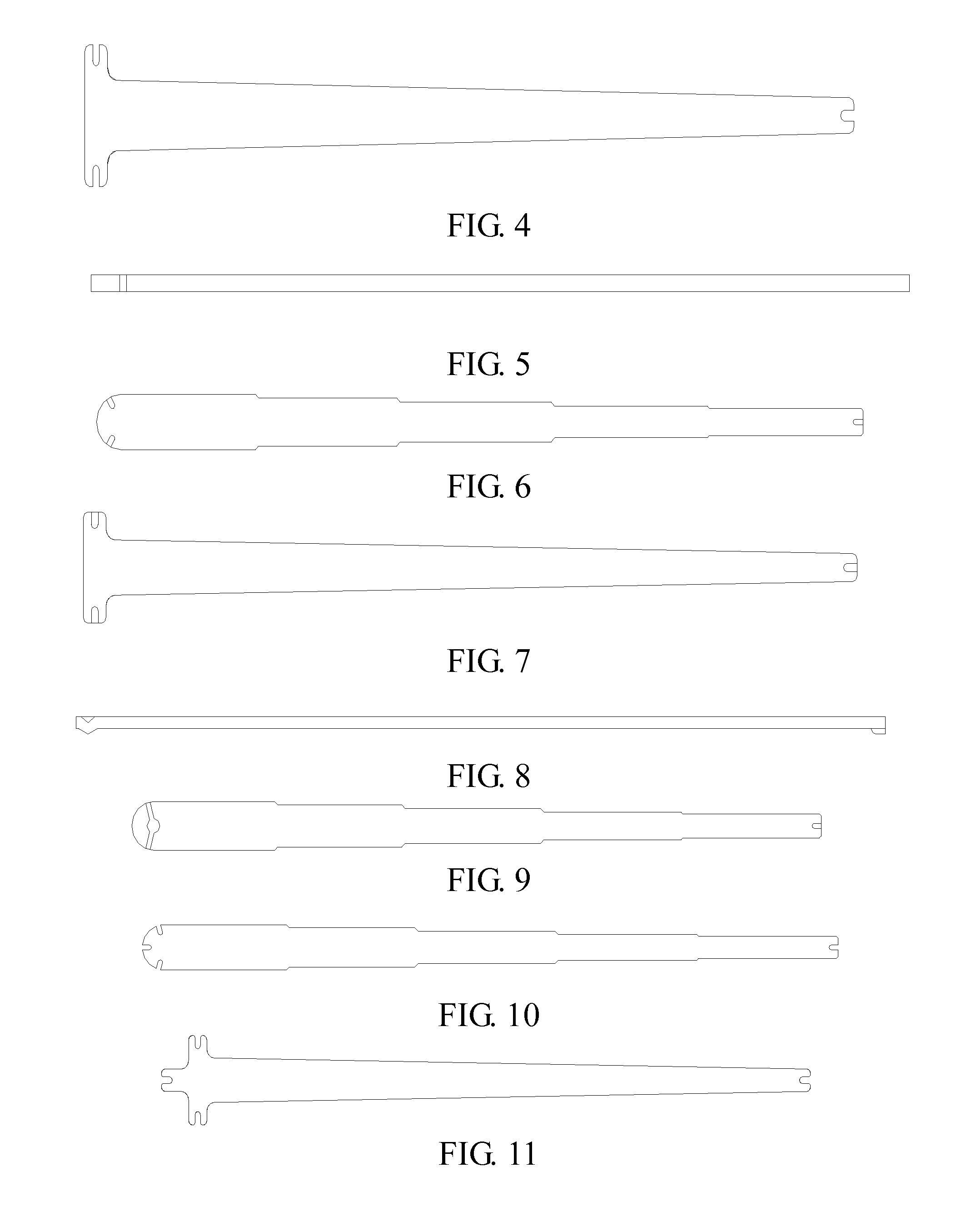
[0045]An inner connecting element of a cavity power divider, which comprises an input end and an output end and is in a sheet form.

[0046]In an implementation, the inner connecting element of the cavity power divider increases in width gradually from the input end to the output end.

[0047]In another implementation, the inner connecting element of the cavity power divider increases in size in a stepped manner from the input end to the output end.

[0048]In a first implementation, the inner connecting element of the cavity power divider is formed with U-shaped notches at the input end and the output end thereof respectively, and specifically, is formed with one U-shaped notch at the input end thereof and formed with at least two U-shaped notches at the output end thereof; the at least two U-shaped notches at the output end are distributed uniformly, and the U-shaped notches are connected with connectors of the cavity power divider respectively.

[0049]In a second implementation,...

Example

Embodiment 2

[0058]A cavity power divider, comprising a cavity and at least three connectors, wherein the cavity is provided with one of the connectors at an input end thereof and at least two of the connectors at an output end thereof, and an inner connecting element is included in the cavity, with an input end and an output end of the connecting element being connected with the input end and the output end of the cavity respectively.

[0059]The inner connecting element is in a sheet form. In a first implementation, the inner connecting element of the cavity power divider is formed with U-shaped notches at the input end and the output end thereof respectively, and specifically, is formed with one U-shaped notch at the input end thereof and formed with at least two U-shaped notches at the output end thereof; the at least two U-shaped notches at the output end are distributed uniformly, and the U-shaped notches are connected with connectors of the cavity power divider respectively.

[0060...

Example

Embodiment 3

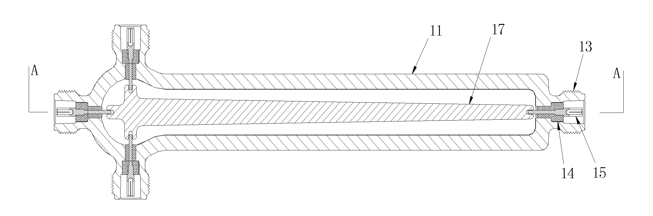
[0075]As shown in FIG. 20 and FIG. 21, a cavity one-to-two power divider comprises a cavity 11, three connectors and a connecting element 12. The cavity is provided with one connector at an input end thereof and with two connectors at an output end thereof. The connecting element 12 is in a sheet form, and an input end and an output end of the connecting element are connected with the connectors respectively. The cavity 11 and the connectors are formed integrally.

[0076]The connecting element 12 is in a sheet form. The connecting element is as described in any of the implementations of Embodiment 1 shown in FIGS. 3 to 9.

[0077]Each of the connectors comprises an outer conductor 13, an inner conductor 15 and an insulator 14. The outer conductor 13 is integrally formed with the cavity 11; the inner conductor 15 is disposed within the outer conductor 13 and connected with the connecting element; and the insulator is disposed between the outer conductor and the inner conductor...


PUM

PropertyMeasurementUnit
Sizeaaaaaaaaaa
Widthaaaaaaaaaa

Abstract

Embodiments of the present disclosure disclose an inner connecting element of a cavity power divider, the cavity power divider and a manufacturing method thereof Two ends of the inner connecting element of the cavity power divider are respectively an input end and an output end, and the inner connecting element of the cavity power divider is in a sheet form. The cavity power divider comprises a cavity and at least three connectors. The cavity is provided with one connector at an input end thereof and with at least two connectors at an output end thereof The connecting element is included in the cavity, with the input end and the output end of the connecting element being connected respectively with the connectors at the input end and the output end of the cavity.

Description

FIELD OF THE INVENTION[0001]The present disclosure generally relates to the technical field of communications, and more particularly, to an inner connecting element of a cavity power divider, the cavity power divider and a manufacturing method of the cavity power divider.BACKGROUND OF THE INVENTION[0002]FIG. 1 shows a structure of a conventional cavity power divider. The cavity power divider comprises connectors 1 and a cavity 2 which has a rectangular cross section. The cavity 2 is provided with one connector at an input end thereof and four connectors at an output end thereof. Each of the connectors comprises an inner conductor 4 therein. Also, a connecting rod 3 in the form of a stepped round body is included in the cavity 2. An end of the connecting rod 3 is connected to the inner conductor of the connector disposed at the input end, and the other end of the connecting rod 3 is connected to inner conductors of the connectors disposed at the output end. The connecting rod 3 is ma...

Claims


Application Information

Patent Timeline
IPC IPC(8): H01P5/12
CPCY10T29/49826H01P5/12
Inventor SUN, SHANGCHUANTONG, ENDONG
Owner ANHUI TATFOOK TECH CO LTD
Why Eureka
Try Eureka