Crucible

a technology of crucibles and crucibles, which is applied in the field of crucibles, can solve the problems of contaminating the upper electrode, requiring a significant amount of power, and requiring a large amount of power, and achieves the effects of less power, less power requirements, and easy withstanding the compressive for

Active Publication Date: 2013-12-19
LECO CORPORATION
View PDF10 Cites 4 Cited by
  • Summary
  • Abstract
  • Description
  • Claims
  • Application Information

AI Technical Summary

Benefits of technology

[0007]The crucible of the present invention is designed to resolve the problems inherent with prior art crucibles, and, unexpectedly, results in a crucible when used in a resistance analytical furnace provides the same fusion temperature of about 3000° C. while requiring up to 30% less power. The crucible is made of a resistive material, such as graphite, and comprises a generally cylindrical body with an open mouth at the top and a pedestal base. An inwardly projecting concave arcuate annular indentation extends between the body and pedestal base with a smoothly curved radius of curvature. The upper and lower walls of the arcuate indentation diverge outwardly at an angle of from about 56° to about 60°. The disk-shaped pedestal base includes, in a preferred embodiment, a bottom surface with a centrally formed circular indentation. The interior floor of the cylindrical body is also concavely rounded with a first radius of curvature and the junction of the floor and the inner side walls of the cylindrical body are likewise curved at a second radius of curvature smaller than the radius of curvature of the central floor. The overall height of the crucible has been increased by about 10% over existing crucibles and, when employed in a resistance analytical furnace, provides even heating at the floor and lower sides of the cylindrical side walls of the body to achieve the desired fusion temperatures at lower power requirements. The crucible design is also robust and easily withstands the compressive force of the upper and lower electrodes during an analysis without fracturing.

Problems solved by technology

These various improvements to the earlier models of resistance furnaces have resulted in improved performance in terms of accuracy and repeatability of sample analysis, Existing furnaces, however, typically require a significant amount of power, and prior crucibles have suffered with hot spots within the crucible which tends to overheat specimens, causing their bubbling.
In some cases, the molten specimens bubble out of the crucible and, in extreme cases, contaminate the upper electrode which is in contact with the open mouth of such crucibles.

Method used


Image

  • Crucible
  • Crucible
  • Crucible

Examples


Embodiment Construction

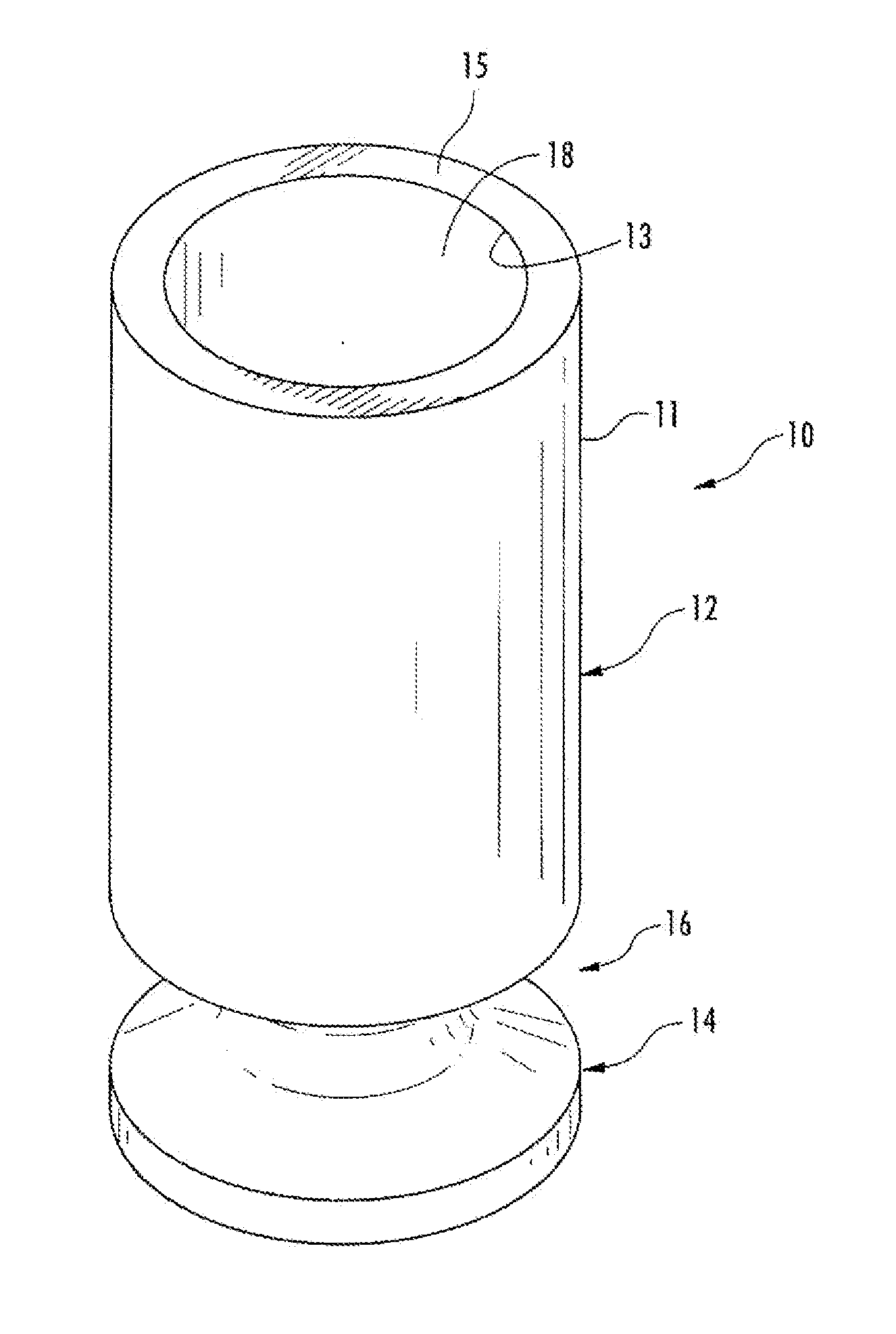
[0014]Referring initially to FIGS. 1 and 4, there is shown a crucible 10 embodying the present invention. Crucible 10 is made of commercial grade graphite and is machined from a solid graphite rod. The crucible has a cylindrical body 12, supported by a pedestal base 14 between which there is an annular inwardly extending concave indentation 16. The crucible has an upper opening 18 at the top for receiving specimens ranging from about 0.1 gram to 1 gram in size. The specimens can be in any form but typically are pins or chips which likewise are frequently encased in a nickel basket serving as an accelerator during the fusion process. The sample can be introduced manually in some systems or preferably by automation through an aperture in the upper electrode and a sample drop mechanism as described in the above-identified U.S. Pat. No. 6,291,802.

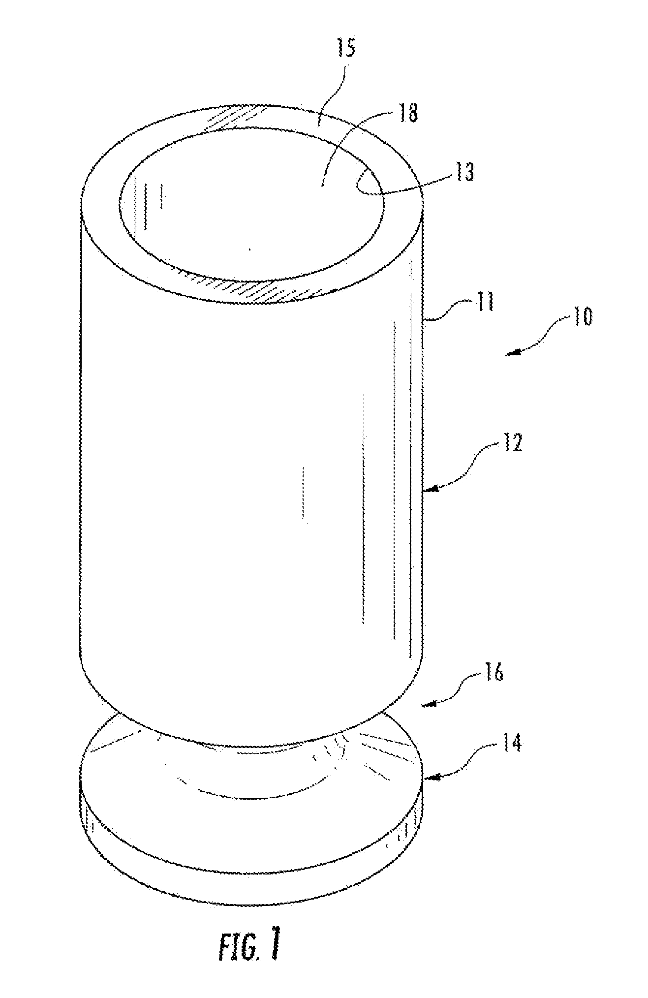
[0015]The cylindrical body 12 includes an outer cylindrical wall 11 and an inner cylindrical wall 13. As seen in FIG. 5, the interior of the c...


PUM


Abstract

A graphite crucible has a cylindrical body with an upper opening for receiving a sample for analysis and a disk-shaped pedestal base. The pedestal base includes a bottom surface with a centrally formed circular indentation. An inwardly projecting concave arcuate annular indentation extends between the body and pedestal base with a smoothly curved radius of curvature. The upper and lower walls of the arcuate indentation diverge outwardly at an angle of from about 56 to about 60°. The pedestal base includes a bottom surface with a centrally formed circular indentation.

Description

CROSS-REFERENCE TO RELATED APPLICATIONS[0001]This application claims priority under 35 U.S.C. §119(e) and the benefit of U.S. Provisional Application No. 61 / 661,603 entitled CRUCIBLE, filed on Jun. 19, 2012, by Joshua N. Wetzel et al., the entire disclosure of which is incorporated herein by reference.BACKGROUND OF THE INVENTION[0002]The present invention relates to crucibles for fusion of a specimen and particularly to crucibles made of a resistive material.[0003]Graphite crucibles are employed in analytical furnaces for fusing specimens to temperatures of about 2500° C. to about 3000° C. with the carbon interacting with the specimen to release gases, which are swept from the furnace area by an inert gas to detectors for subsequent determination of elements such as hydrogen, nitrogen, and oxygen. A current example of such an analytical instrument is an ONH836 furnace and analyzer available from Leco Corporation of St. Joseph, Mich. Such instruments employ a pair of electrodes, whic...

Claims


Application Information

Patent Timeline
Patent Type & Authority Applications(United States)
IPC IPC(8): B01L3/04F27B14/06
CPCB01L3/04F27B14/06B01L2300/0851B01L2300/12F27B14/10
Inventor WETZEL, JOSHUA N.FORD, GORDON C.
Owner LECO CORPORATION
Why Eureka
Try Eureka