Anchor with angular adjustment

a technology of anchoring system and angular adjustment, which is applied in the direction of building components, building reinforcements, construction, etc., can solve the problems of unintentional movement and reduce the ability of the anchoring system to transfer tension

Active Publication Date: 2013-12-26
HOHMANN & BARNARD INC
View PDF0 Cites 42 Cited by
  • Summary
  • Abstract
  • Description
  • Claims
  • Application Information

AI Technical Summary

Benefits of technology

[0003]In one aspect, a wall anchor for use in a cavity wall to connect to a veneer tie to join an inner wythe and an outer wythe of the cavity wall generally includes an elongated body having a driven end, a driving end, and a longitudinal axis. A collar is mounted on the elongated body for rotation about the longitudinal axis of the elongated body. The collar is adapted for connection to the veneer tie. A rotation control structure operatively engages the collar and elongate body. The rotation control structure permits rotation of the collar in a first direction relative to the elongate body about the longitudinal axis of the elongate body. The rotation control structure prevents rotation of the collar relative to the elongate body about the longitudinal axis of the elongate body in a second direction opposite the first direction. The rotation control structure comprises ratchet teeth associated with one of the elongate body and the collar and a pawl associated with the other of the elongate body and the collar.

Problems solved by technology

Slight angular and height misalignments in an installed veneer tie can reduce the ability of the anchoring system to transfer tension and compression loads acting on the outer wythe to the backup wall.
However, a freely adjustable anchoring system is not preferable, because of the risk of unintentional movement of the anchor prior to connection to the veneer tie.

Method used


Image

  • Anchor with angular adjustment
  • Anchor with angular adjustment
  • Anchor with angular adjustment

Examples


Embodiment Construction

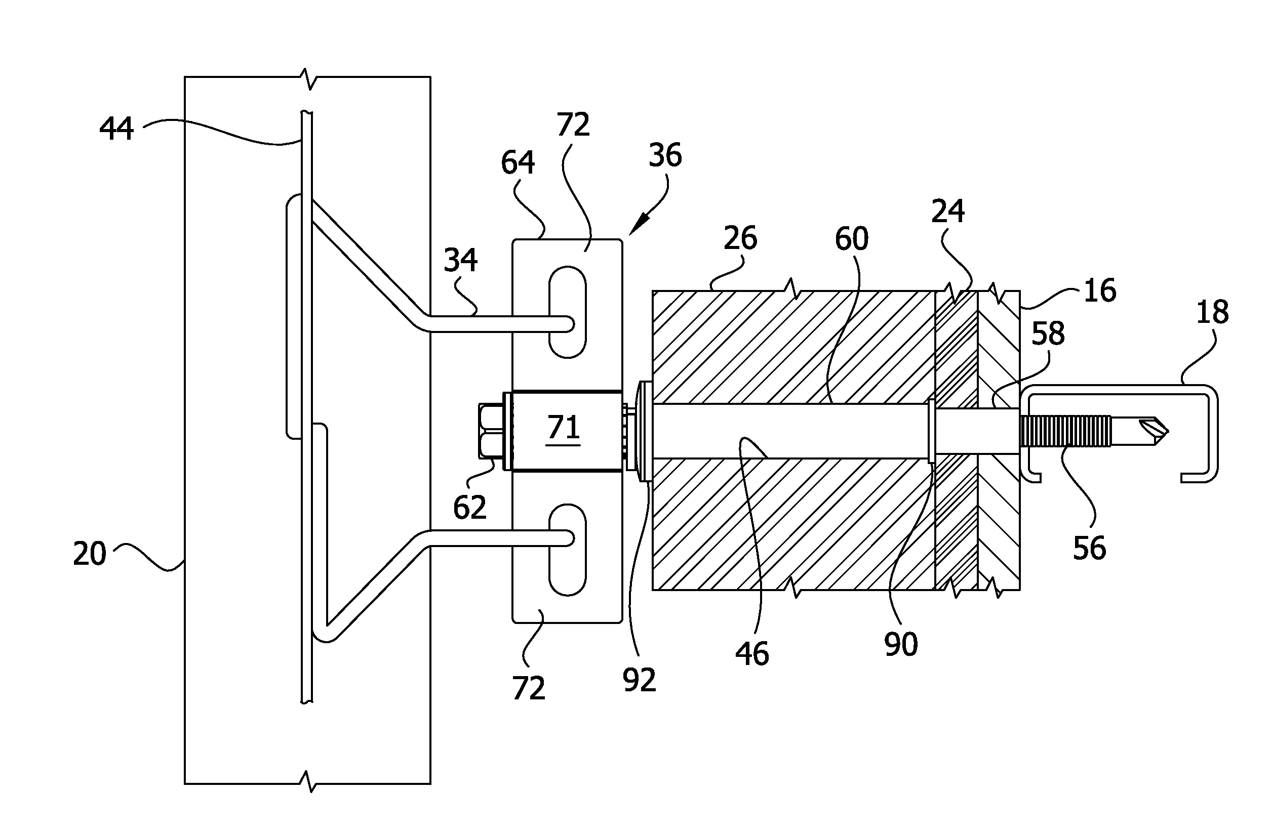
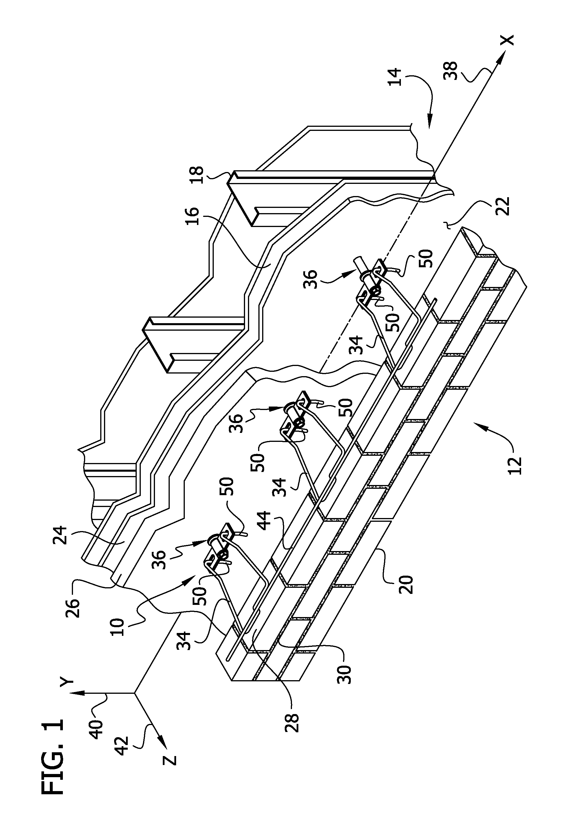
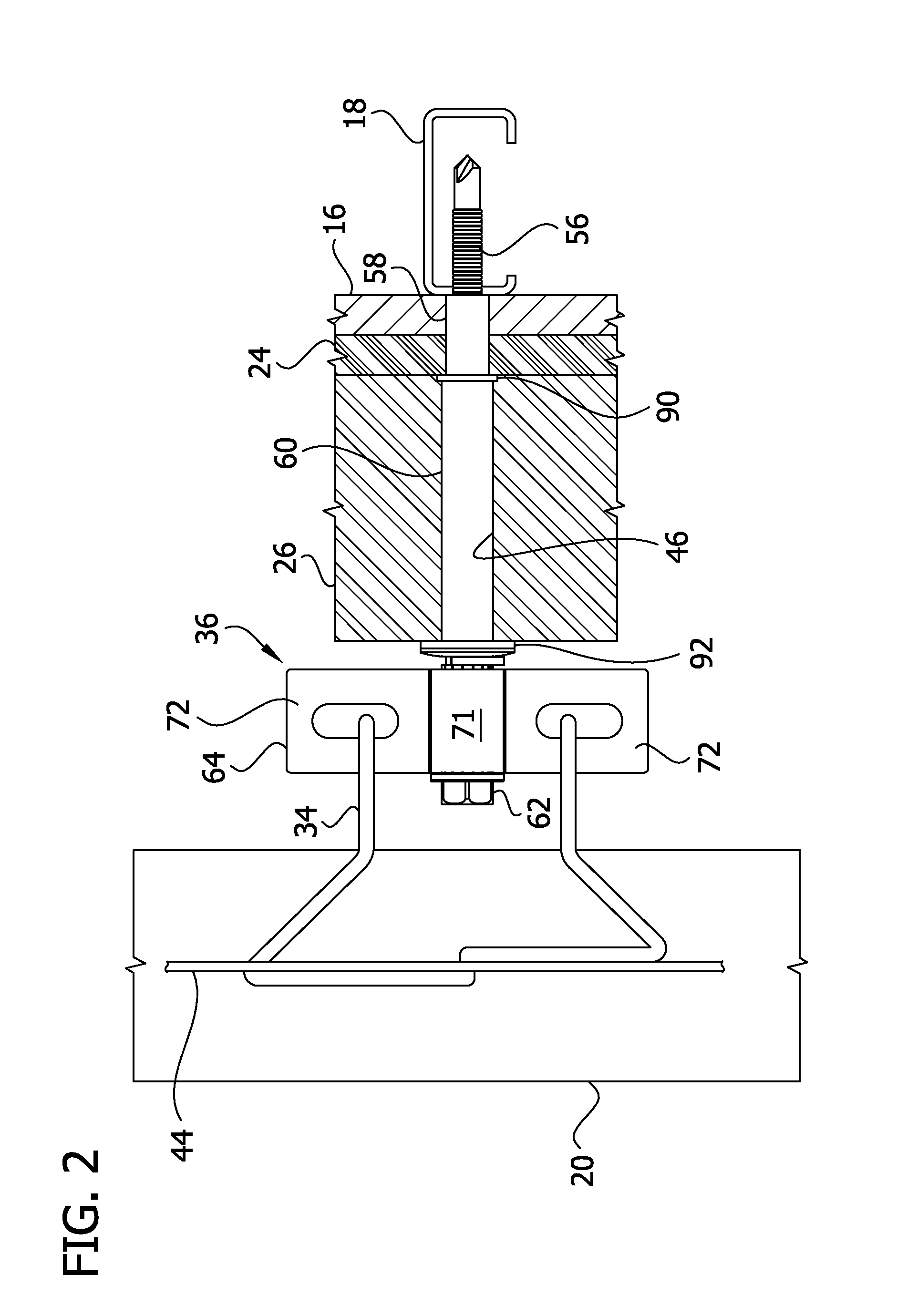
[0019]Referring to FIG. 1, an anchoring system for cavity walls is indicated generally at 10. A cavity wall structure generally indicated at 12 comprises an inner wythe or drywall backup 14 with sheetrock or wallboard 16 mounted on metal columns or studs 18 and an outer wythe or facing wall 20 of brick construction. Between the inner wythe 14 and the outer wythe 20, a cavity 22 is formed. An air / vapor barrier 24 and insulation 26 are attached to an exterior surface of the inner wythe 14. The construction of the inner and outer wythes may be other than described without departing from the scope of the present invention.

[0020]Successive bed joints 28 and 30 are substantially planar and horizontally disposed and, in accordance with building standards, are approximately 0.375 inches in height in the a typical embodiment. Selective ones of bed joints 28 and 30, which are formed between courses of bricks, are able to receive the insertion portion of a veneer tie 34. A wall anchor 36 is th...


PUM


Abstract

A wall anchor for use in an insulated cavity wall has an elongated body extending from a driven end to a driving end. The driven end is adapted to be mounted on an inner wythe of a cavity wall structure. A rotation control portion of the elongated body may include teeth formed on the surface. A collar with at least one aperture for a veneer tie is located near the driving end. The collar may have a pawl associated with it and positioned to engage the teeth on the elongated body. The teeth of the elongated body and the pawl of the collar form a ratchet structure. The collar can be rotated relative to the wall anchor only in a single direction, with the interengaging ratchet structure preventing rotation in the opposite direction.

Description

FIELD OF THE INVENTION[0001]The present invention generally relates to anchoring systems for insulated cavity walls, and more specifically, a wall anchor that is adjustable for proper positioning of a veneer tie.BACKGROUND OF THE INVENTION[0002]Anchoring systems for cavity walls are used to secure veneer facings to a building and overcome seismic and other forces, e.g. wind shear, etc. Anchoring systems generally include a wall anchor for insertion into an inner wythe of a cavity wall structure and a veneer tie that is embedded in a mortar joint of an outer wythe or brick veneer. Slight angular and height misalignments in an installed veneer tie can reduce the ability of the anchoring system to transfer tension and compression loads acting on the outer wythe to the backup wall. However, a freely adjustable anchoring system is not preferable, because of the risk of unintentional movement of the anchor prior to connection to the veneer tie.SUMMARY OF THE INVENTION[0003]In one aspect, ...

Claims


Application Information

Patent Timeline
Patent Type & Authority Applications(United States)
IPC IPC(8): E04B1/41
CPCE04B1/4178
Inventor HOHMANN, JR., RONALD P.
Owner HOHMANN & BARNARD INC
Why Eureka
Try Eureka