Method and module for measuring the rate of change of frequency of waveforms related to converter units in wind turbine generators

a technology of converter units and waveforms, applied in the direction of noise figure or signal-to-noise ratio measurement, electric generator control, instruments, etc., can solve the problems of affecting the operation of the generator

Active Publication Date: 2013-12-26
GAMESA INNOVATION & TECH SA
View PDF5 Cites 21 Cited by
  • Summary
  • Abstract
  • Description
  • Claims
  • Application Information

AI Technical Summary

Benefits of technology

[0012]Some of the objects and problems mentioned above are solved by a method and module according to the present invention. Namely, the present invention describes a method for measuring the rate of change of frequency of waveform related to a converter unit of a wind turbine generator, said method comprising the steps of measuring an instantaneous value of a frequency value of said waveform related to said converter unit, calculating a first filtered value (ROCOF-F1) of said rate of change of frequency (ROCOF) based on said instantaneous frequency value, said first filtered value (ROCOF-F1) having a measurement error lower than a first predetermined measurement error (DB-ROCOF-F1), said first filtered value (ROCOF-F1) having a time response slower than a predetermined time response requirement (t1), and, calculating a second filtered value (ROCOF-F2) of said rate of change of frequency (ROCOF) based on said instantaneous frequency value, said second fi

Problems solved by technology

This method is, however, very sensitive to noise in the voltage waveform and typically requires several voltage waveforms before a measured can be determined.
When measuring the rate of change (ROCOF) noise a critical issue.
This noise comes from the grid voltage and also from harmonics of the grid voltage.
Furthermore, the derivative nature of ROCOF causes noise to be amplified and even wor

Method used


Image

  • Method and module for measuring the rate of change of frequency of waveforms related to converter units in wind turbine generators
  • Method and module for measuring the rate of change of frequency of waveforms related to converter units in wind turbine generators
  • Method and module for measuring the rate of change of frequency of waveforms related to converter units in wind turbine generators

Examples


Embodiment Construction

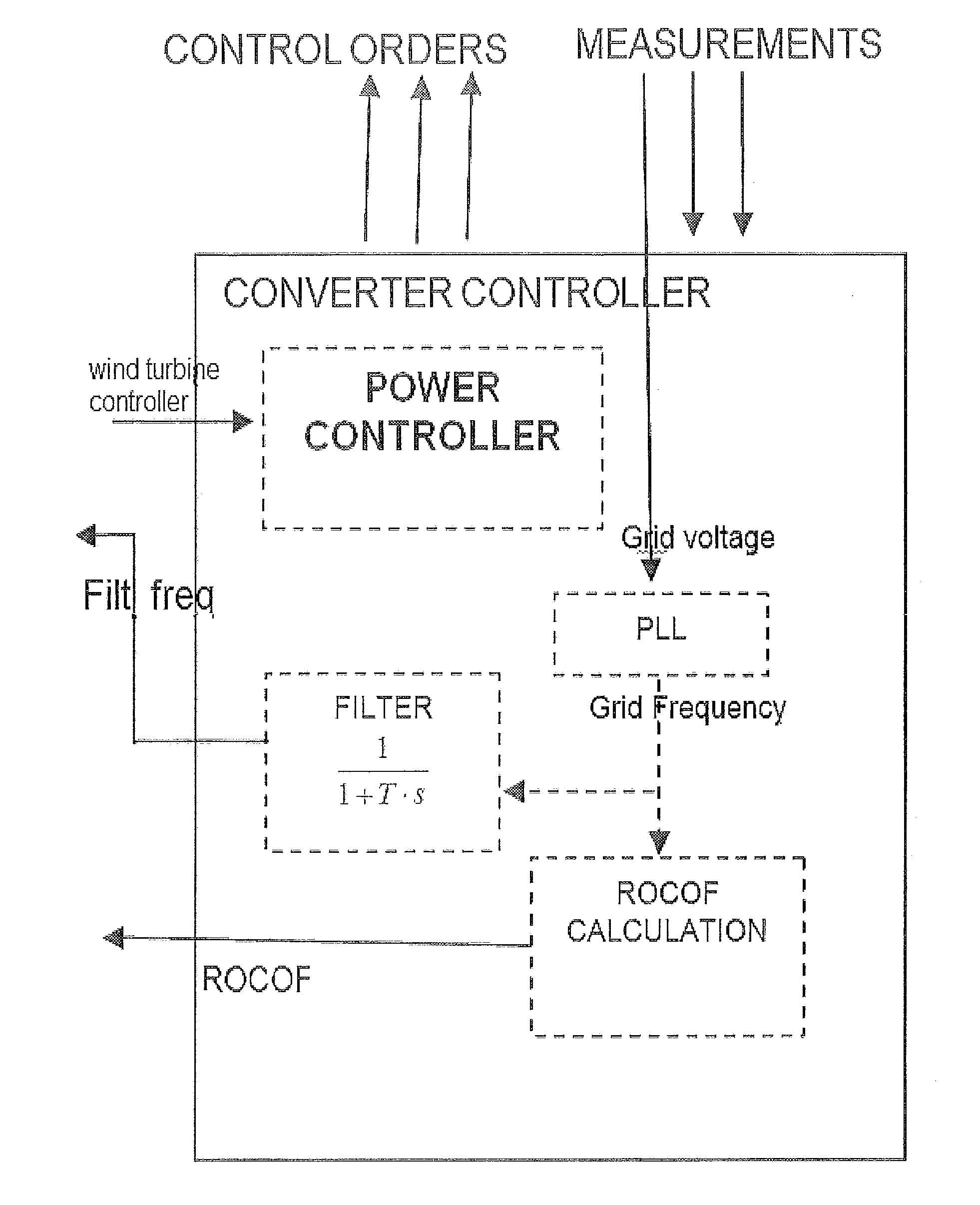
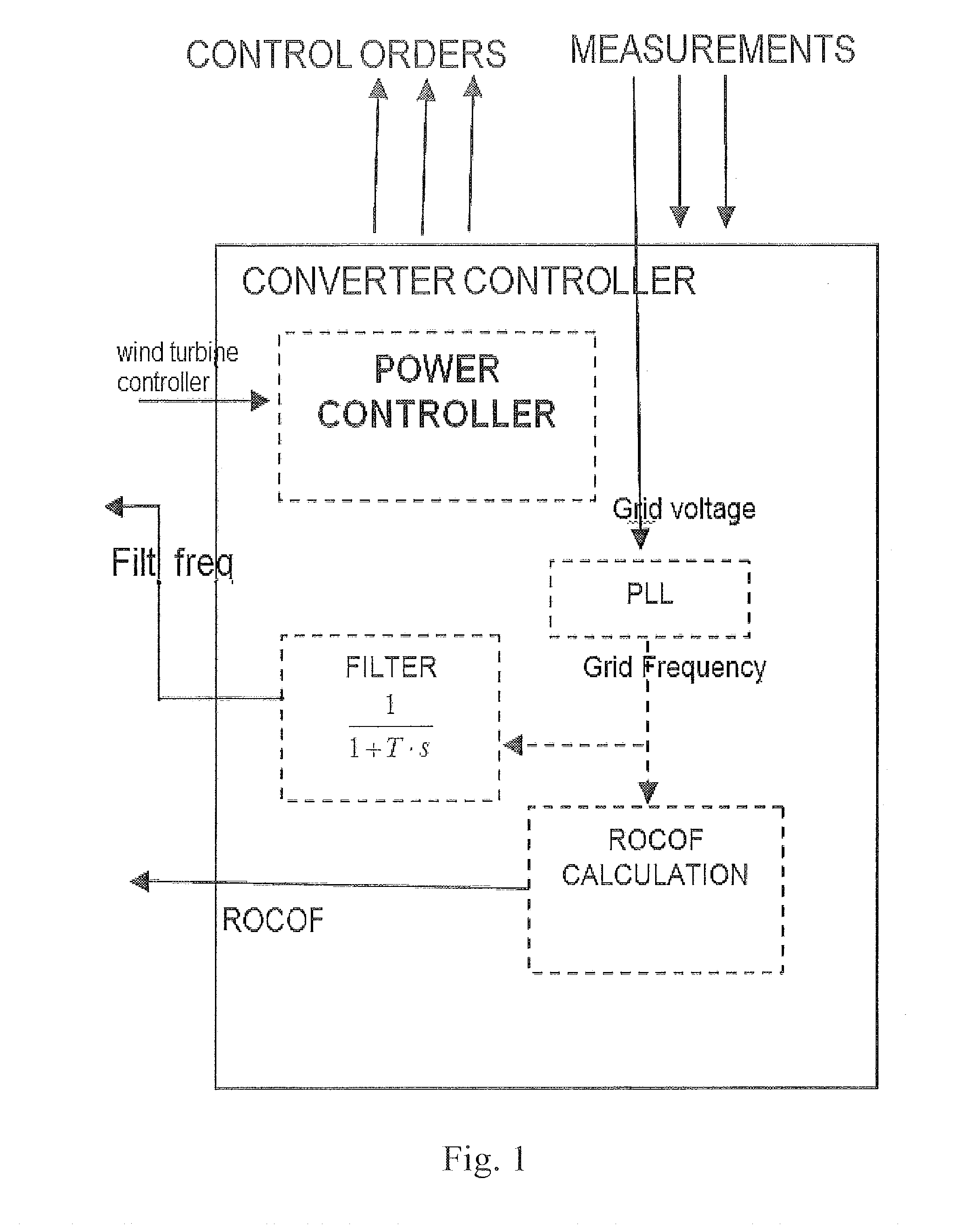
[0026]FIG. 1 shows a converter controller of a converter unit for a wind turbine generator. The present invention relates to variable speed wind turbines that are connected to the grid and the effects of a change of grid frequency. It is important to have an accurate and quick measurement of the frequency and the rate of change of frequency of the grid voltage so as to adapt the operation of the wind turbine generator to the new grid condition.

[0027]Typically wind turbine controllers need the frequency and rate of frequency measurements that show a quick time response, typically being 200 ms or less. This quick time requirement is a tight requirement for the measurement unit within the converter controller.

[0028]A Voltage waveform in the converter unit is the preferred variable to be measured. However, other variables based on current and / or other voltage and power parameters may be used.

[0029]A preferred method for measuring the frequency of the grid voltage waveform is to use stat...


PUM


Abstract

Method and module for measuring the rate of change of frequency of a waveform related to a converter unit of a wind turbine generator, comprising: measuring an instantaneous value of said rate of change of frequency of the waveform, calculating a first filtered value of said rate of change of frequency, said first filtered value having good accuracy but low time response, and calculating a second filtered value of said rate of change of frequency said second filtered value having a good time response but low accuracy, comparing said first and second filtered values and selecting that an output value of said measured rate of change is based on said first or second filtered values depending on said comparison.

Description

FIELD OF THE INVENTION[0001]The present invention refers to a method and a module of measuring the rate of change of frequency for waveforms related to converter units, preferably in wind turbines.BACKGROUND OF THE INVENTION[0002]Controller modules and systems for converter units in wind turbines require accurate operation while keeping a good time response.[0003]For measuring the rate of change of frequency prior art documents disclose analog and digital measurement alike. US003032715 describes an analog frequency measurement by CCU with structural code. GB2159963 describe a measurement system based on counting the period of the voltage waveform as used in state of the art relays for measuring the rate of change of frequency.[0004]The use of relays for measuring parameters relating to frequencies are well known. In electrical systems, a rate of change relay detects the zero crossings of a generator voltage. The relay then measures the time between the zero crossing and calculates a...

Claims


Application Information

Patent Timeline
IPC IPC(8): G01R23/167F03D9/00
CPCG01R23/167F03D9/003G01R23/00F03D9/25F03D9/255Y02E10/72
Inventor JIMENEZ BUENDIA, FRANCISCO
Owner GAMESA INNOVATION & TECH SA
Why Eureka
Try Eureka