MCP unit, MCP detector and time of flight mass spectrometer

a mass spectrometer and detector technology, applied in the direction of instruments, particle separator tube details, separation processes, etc., can solve the problems of inability to perform waveform shaping of detected peak, many manufacturing difficulties in rendering channel diameter small, and inability to extend the time of flight. , to achieve the effect of inhibiting the time spreading of secondary electrons

Active Publication Date: 2009-07-21
HAMAMATSU PHOTONICS KK
View PDF13 Cites 52 Cited by
  • Summary
  • Abstract
  • Description
  • Claims
  • Application Information

AI Technical Summary

Benefits of technology

[0015]As described above, in the MCP unit according to the present invention, an arrangement condition among three kinds of electrodes such as the MCP, the acceleration electrode, and the anode is adjusted. Thus, it becomes possible to reduce a full width at half maximum (FWHM) of a peak appearing on a detected time spectrum. That is, the adjustment of the distance A between the MCP and the acceleration electrode contributes to control of a rise time of a detected peak, and the adjustment of the distance B between the acceleration electrode and the anode contributes to control of a fall time of the detected peak. In other words, the acceleration electrode is arranged between the MCP and the anode so that a condition of A<B is satisfied, and thus, it becomes possible to greatly shorten the fall time of the detected peak, thereby improving the time response characteristic. For example, in the TOF-MS, the FWHM of the detected peak appearing in the time spectrum in each charged particle different in mass is reduced. Thus, as a result of the MCP unit being applied, it becomes possible to remarkably improve the time response characteristic.
[0018]In the MCP unit according to the present invention, an effective area in the acceleration electrode is preferably wider than an effective area (an area in which a channel for releasing secondary electrons is formed) of the exit surface in the MCP. The reason for this is that a collision of the secondary electrons with the acceleration electrode is inhibited, improving detection sensibility.
[0020]The MCP unit according to the present invention may further comprise a delay electrode arranged between the exit surface of the MCP and the acceleration electrode. The delay electrode also includes, similar to the acceleration electrode, a plurality of openings which permit passing of the secondary electrons migrating from the exit surface of the MCP toward the anode. In particular, the delay electrode is preferably set equal to or lower in potential than the second electrode. The opening ratio of the delay electrode is preferably 60% to 95%, similar to the acceleration electrode. In particular, when the delay electrode is set lower in potential than the second electrode, it becomes possible to eliminate secondary electrons of low energy, thereby further inhibiting a time spreading of the secondary electrons; as compared to a case where the acceleration electrode is arranged. In this case, the delay electrode is preferably arranged in a position so that a shortest distance to the exit surface of the MCP is longer than a shortest distance to the acceleration electrode.

Problems solved by technology

Then, the inventors have studied in detail the above-described conventional MCP detector, and as a result, have found problems as follows.
However, the extension of the time of flight cannot be performed by the existing TOF-MS device.
Additionally, in the conventional MCP detector, even when the arrangement of the MCP and the anode is adjusted, a rise time and a fall time of the detected peak in the time spectrum are changed in an associated manner, and thus, it is not possible to perform waveform shaping of the detected peak.
However, many manufacturing difficulties are found in rendering the channel diameter small while maintaining a large effective diameter, which is a characteristic of the MCP.
In particular, when the channel diameter is small, a thickness of the MCP itself results in being relatively thin.
This causes a bending or the like to be produced.

Method used


Image

  • MCP unit, MCP detector and time of flight mass spectrometer
  • MCP unit, MCP detector and time of flight mass spectrometer
  • MCP unit, MCP detector and time of flight mass spectrometer

Examples


first embodiment

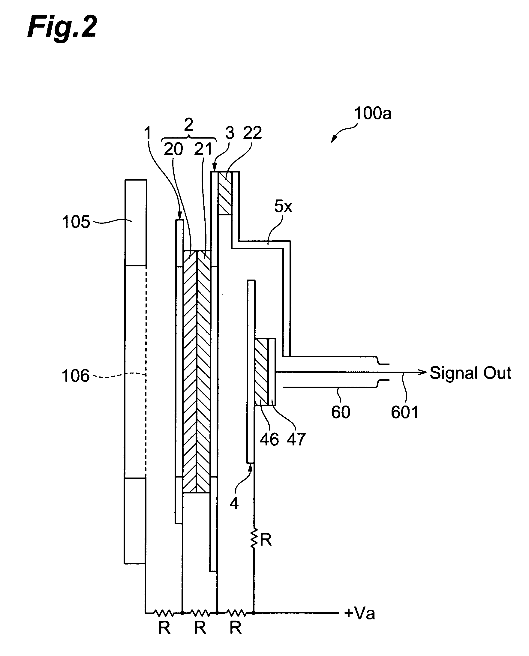
[0047]FIG. 3 is an assembly process chart showing a configuration of the first embodiment of the MCP detector according to the present invention. FIG. 4 is a diagram showing a cross-sectional structure, along the line I-I in FIG. 3, of the MCP detector according to the first embodiment. FIG. 5 is an equivalent circuit diagram of the MCP detector according to the first embodiment shown in FIGS. 3-4.

[0048]The MCP detector according to the first embodiment has a configuration in which an IN-electrode 1 (first electrode), an MCP cluster 2, an OUT-electrode 3 (second electrode), an acceleration electrode 5, and an anode electrode 4 (third electrode) are arranged in this order along a tube axis (reference axis) AX. The MCP cluster 2 is constituted by two disk-shaped MCPs 20, 21. On an incident surface (front surface where charged particles reach) side of the MCP cluster 2, the IN-electrode 1 (first electrode) is arranged, while on an exit surface (rear surface) side thereof, the OUT-elect...

second embodiment

[0079]Subsequently, a second embodiment of the MCP detector according to the present invention is described in detail with reference to FIGS. 15 to FIG. 18. In the MCP detector according to the above-described first embodiment, the floating anode structure is adopted; and in the MCP detector according to the second embodiment, a grounded anode structure is adopted.

[0080]FIG. 15 is an assembly process chart showing a configuration of the second embodiment of the MCP detector according to the present invention. FIG. 16 is a diagram showing a cross-sectional structure, along the line II-II in FIG. 15, of the MCP detector according to the second embodiment. FIG. 17 is an equivalent circuit diagram of the MCP detector according to the second embodiment shown in FIGS. 15 to 16. FIG. 18 is an assembly process chart of the MCP detector according to the second embodiment, in which a 2-terminal structure is adopted as a modification of the voltage application structure.

[0081]The MCP detector ...


PUM


Abstract

The present invention relates to an MCP unit or the like having a structure intended to achieve a desired time response characteristic, without depending on a limitation imposed by a channel diameter of MCP. The MCP unit comprises the MCP for releasing secondary electrons internally multiplied in response to incidence of charged particles, an anode arranged in a position where the secondary electrons reach, and an acceleration electrode arranged between the MCP and the anode. In particular, the acceleration electrode includes a plurality of openings which permit passing of the secondary electrons migrating from the MCP toward the anode. Further, the acceleration electrode is arranged such that the shortest distance B between the acceleration electrode and the anode is longer than the shortest distance A between the MCP and the acceleration electrode. Thus, an FWHM of a detected peak appearing in response to the incidence of the charged particles is remarkably shortened.

Description

BACKGROUND OF THE INVENTION[0001]1. Field of the Invention[0002]The present invention relates to an MCP unit having a multiplying function of charged particles such as electrons and ions, an MCP detector including the MCP unit, and a time-of-flight mass spectrometer including the MCP detector, as relevant parts of a detector used for time-of-flight mass spectrometry or the like.[0003]2. Related Background Art[0004]As a method of detecting a polymer molecular weight, time-of-flight mass spectrometry (TOF-MS) is known. FIG. 1 is a diagram for describing a configuration of an analyzing device (hereinafter, referred to as a TOF-MS device) by the TOF-MS.[0005]As shown in FIG. 1, in the TOF-MS device, a detector 100 is arranged at one end in a vacuum chamber 110, and a sample (ion source) 120 is arranged at the other end in the vacuum chamber 110. Between the detector 100 and the sample 120, a ring-shaped electrode 130 (ion accelerator) having an opening is arranged. The electrode 130 is ...

Claims


Application Information

Patent Timeline
Patent Type & Authority Patents(United States)
IPC IPC(8): H01J37/252
CPCH01J49/025H01J43/246
Inventor HAYASHI, MASAHIROWASHIYAMA, YUUYASUZUKI, AKIOIGUCHI, MASAHIKO
Owner HAMAMATSU PHOTONICS KK
Why Eureka
Try Eureka