Electric power supply apparatus
- Summary
- Abstract
- Description
- Claims
- Application Information
AI Technical Summary
Benefits of technology
Problems solved by technology
Method used
Image

Examples
first modified example
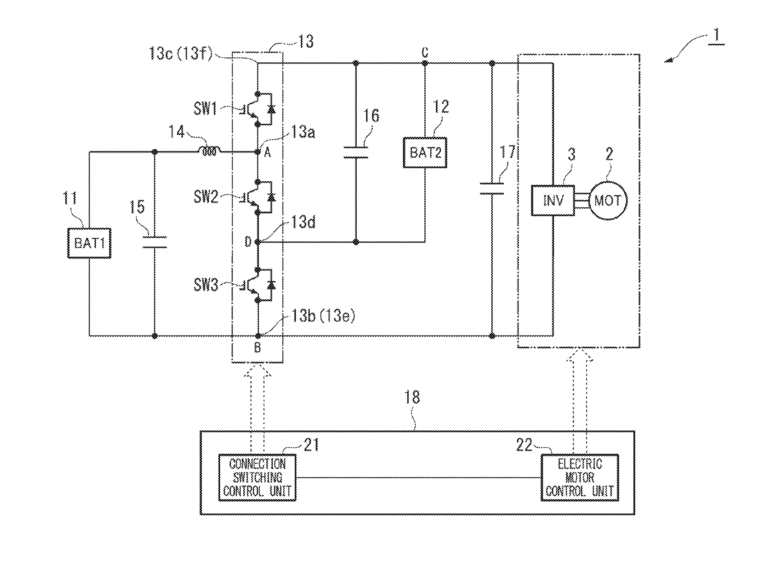
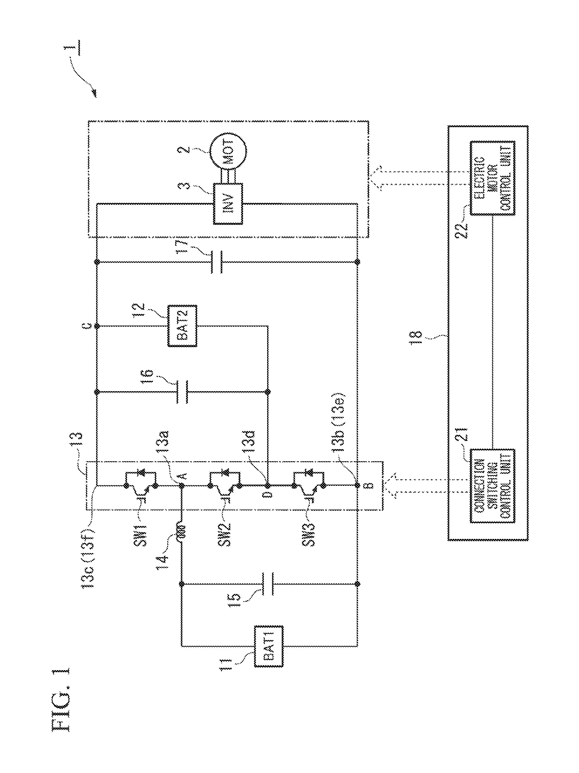
[0134]In addition, in the embodiment described above, considering the electric power supply apparatus 1, for instance, shown in FIG. 1 as an example, as the electric power supply apparatus 1 according to a first modified example, for instance, shown in FIG. 7, the electric power supply apparatus 1 may include a second reactor 31 that is provided between the fourth node D and the second electric power supply 12.
[0135]More specifically, a first end of the second reactor 31 is connected between the emitter of the second switching device SW2 and the collector of the third switching device SW3 of the switch circuit 13, and a second end of the second reactor 31 is connected to the negative terminal of the second electric power supply 12.
[0136]In addition, in this first modified example, the reactor 14 and the second reactor 31 are, for example, as shown in FIG. 8, may be magnetically coupled by being wound around a common core 32 such that the magnetic paths are shared.
[0137]In this first...
second modified example , third modified example
Second Modified Example, Third Modified Example
[0184]In addition, in the embodiment described above, for example, in place of the reactor 14, as the electric power supply apparatus 1 according to a second modified example, for instance, shown in FIG. 16, or as the electric power supply apparatus 1 according to a third modified example, thr instance, shown in FIG. 17, a third reactor 41 or a fourth reactor 42 that is provided between the inverter 3 as the electric load and any one of the two output terminals 13e and 13f, may be included.
[0185]According to these second and third modified examples, the single reactor (specifically, the third reactor 41 or the fourth reactor 421) makes it possible to charge and discharge equally the first electric power supply 11 and the second electric power supply 12 equally at the voltage increasing-decreasing time when the voltage of both ends of the reactor is increased and decreased.
[0186]Thereby, it is possible to distribute the burden of the cha...
fourth modified example
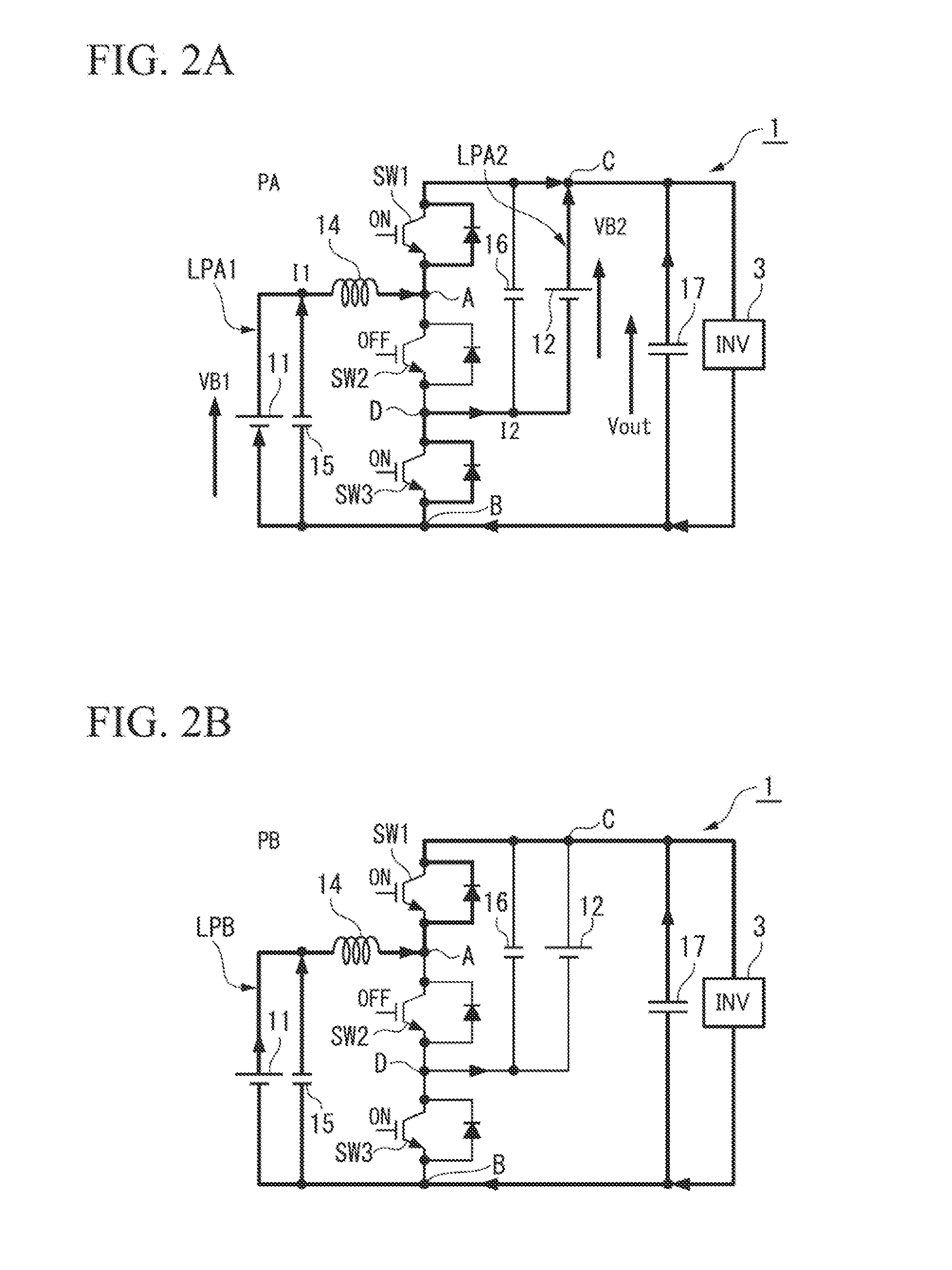
[0187]In addition, in the embodiment described above, the first switching device SW1 and the third switching device SW3 are set to be closed (ON) and the second switching device SW2 is set to be open (OFF) in the parallel mode PA, but the present invention is not limited hereto. For example, in a case where the series mode SA is switched to the parallel mode PA or the like, a constant current control for resolving an unbalance between the voltage VB1 of the first electric power supply 11 and the voltage VB2 of the second electric power supply 12 may be further performed.
[0188]An operation of the electric power supply apparatus 1 according to the fourth modified example of this embodiment described above, specifically, a process that alternately switches between the series state SB and the parallel state PB will be described below.
[0189]First, for example, in a step S01 shown in FIG. 18, the routine obtains a connection state of the switch circuit 13 corresponding to the operation mo...
PUM
 Abstract
Description
Claims
Application Information
 - R&D
- Intellectual Property
- Life Sciences
- Materials
- Tech Scout
- Unparalleled Data Quality
- Higher Quality Content
- 60% Fewer Hallucinations
Browse by: Latest US Patents, China's latest patents, Technical Efficacy Thesaurus, Application Domain, Technology Topic, Popular Technical Reports.
© 2025 PatSnap. All rights reserved.Legal|Privacy policy|Modern Slavery Act Transparency Statement|Sitemap|About US| Contact US: help@patsnap.com