Fast startup control circuit for switch mode power supply

a control circuit and power supply technology, applied in the direction of dc-dc conversion, power conversion systems, instruments, etc., can solve the problems of increasing power consumption, not providing sufficient operating power, and conventional techniques for reducing startup time that are not desirable, so as to speed up the startup process, reduce startup time, and speed up the effect of startup

Active Publication Date: 2013-12-26
BCD SEMICON MFG +1
View PDF5 Cites 20 Cited by
  • Summary
  • Abstract
  • Description
  • Claims
  • Application Information

AI Technical Summary

Benefits of technology

[0006]The present invention relates generally to the field of switch mode power supply (SMPS). More particularly, embodiments of the invention disclose a switching power supply circuit having a fast startup time. Convention techniques for reducing startup time are not desirable. For example, using a smaller startup resistor can speed up the startup process, but it increases power consumption. Alternatively, using a smaller startup capacitor may help to reduce the startup time, but it may not provide sufficient operating power. In embodiments of the present invention, the faster startup is achieved without altering other desirable circuit parameters such as startup resistor or startup capacitor. In an embodiment, a startup resistor is connected to an input of a power switch. During startup, the controller is configured to cause the power switch to amplify a startup current from an external input voltage through the startup resistor and provide a startup power to the controller. During normal operation, the controller is configured to provide a power switch control signal to turn on and off the power switch for controlling a current flow in the primary winding and regulating an output of the power supply. In embodiments of the present invention, the amplification of the power switch is used to amplify the startup current and speed up the startup process.

Problems solved by technology

Convention techniques for reducing startup time are not desirable.
For example, using a smaller startup resistor can speed up the startup process, but it increases power consumption.
Alternatively, using a smaller startup capacitor may help to reduce the startup time, but it may not provide sufficient operating power.

Method used


Image

  • Fast startup control circuit for switch mode power supply
  • Fast startup control circuit for switch mode power supply
  • Fast startup control circuit for switch mode power supply

Examples


Embodiment Construction

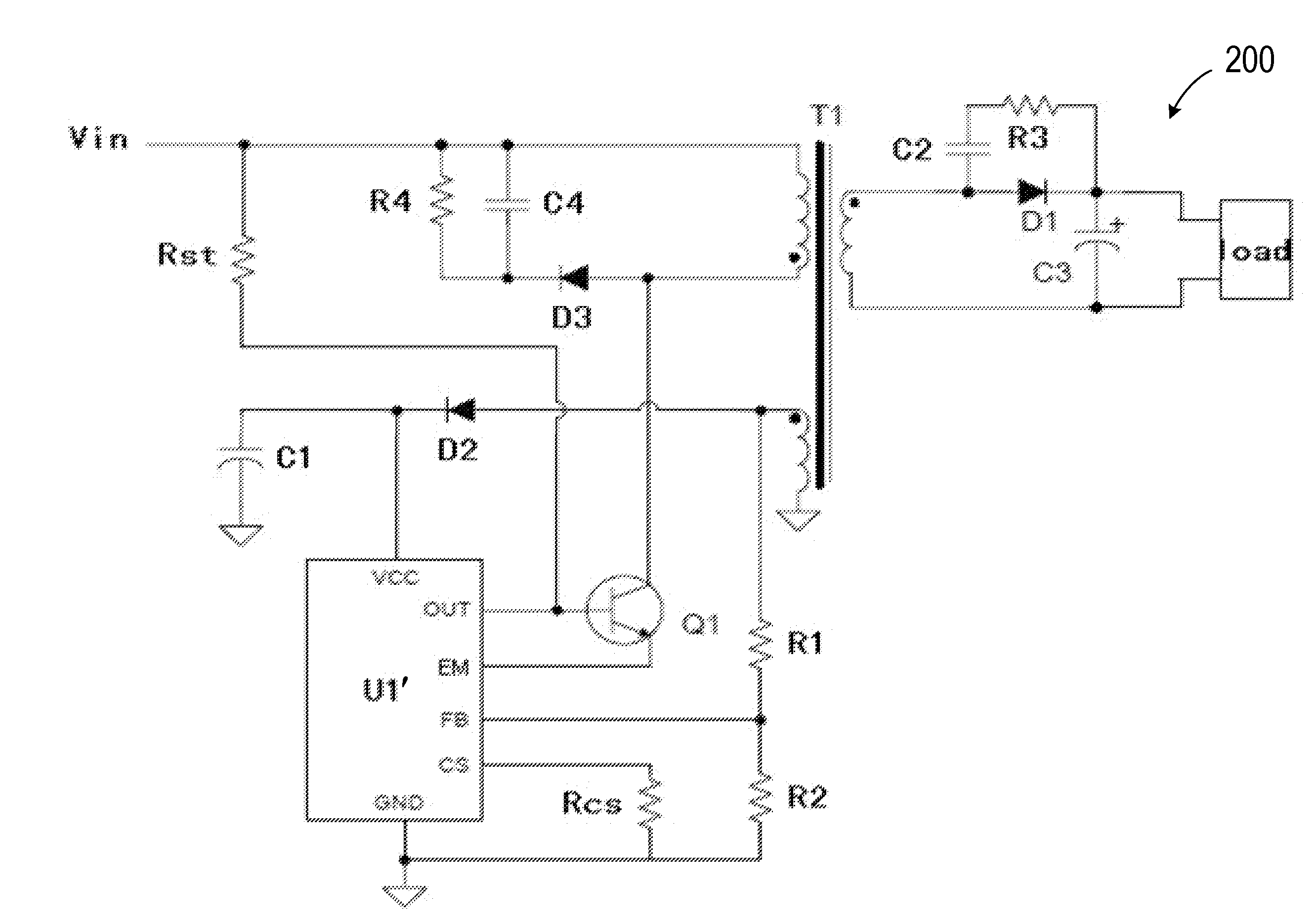
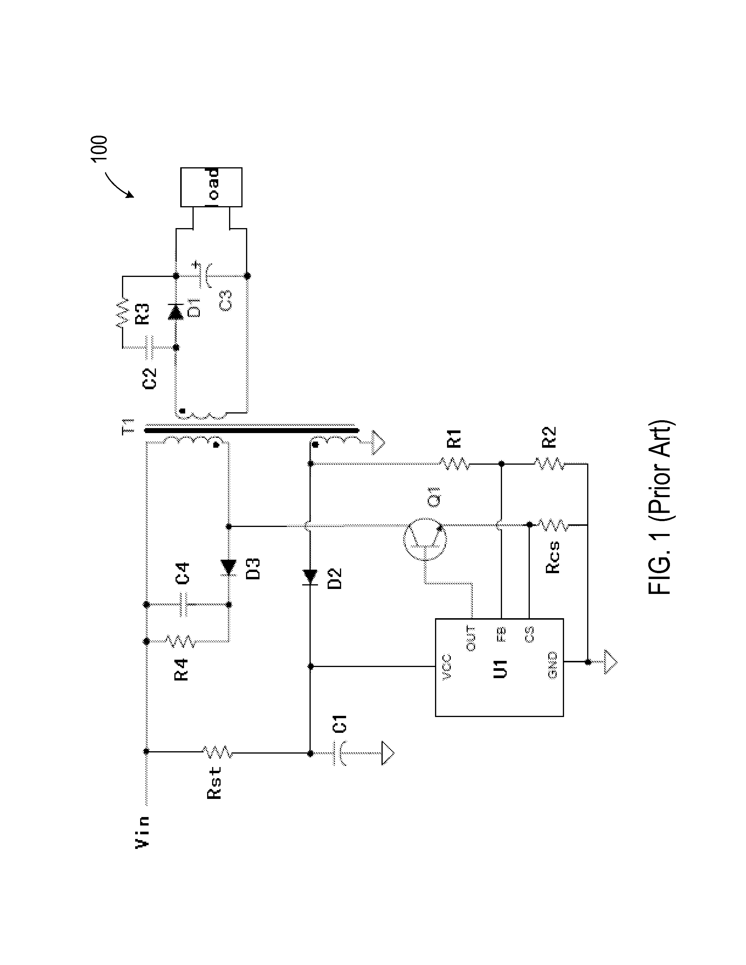
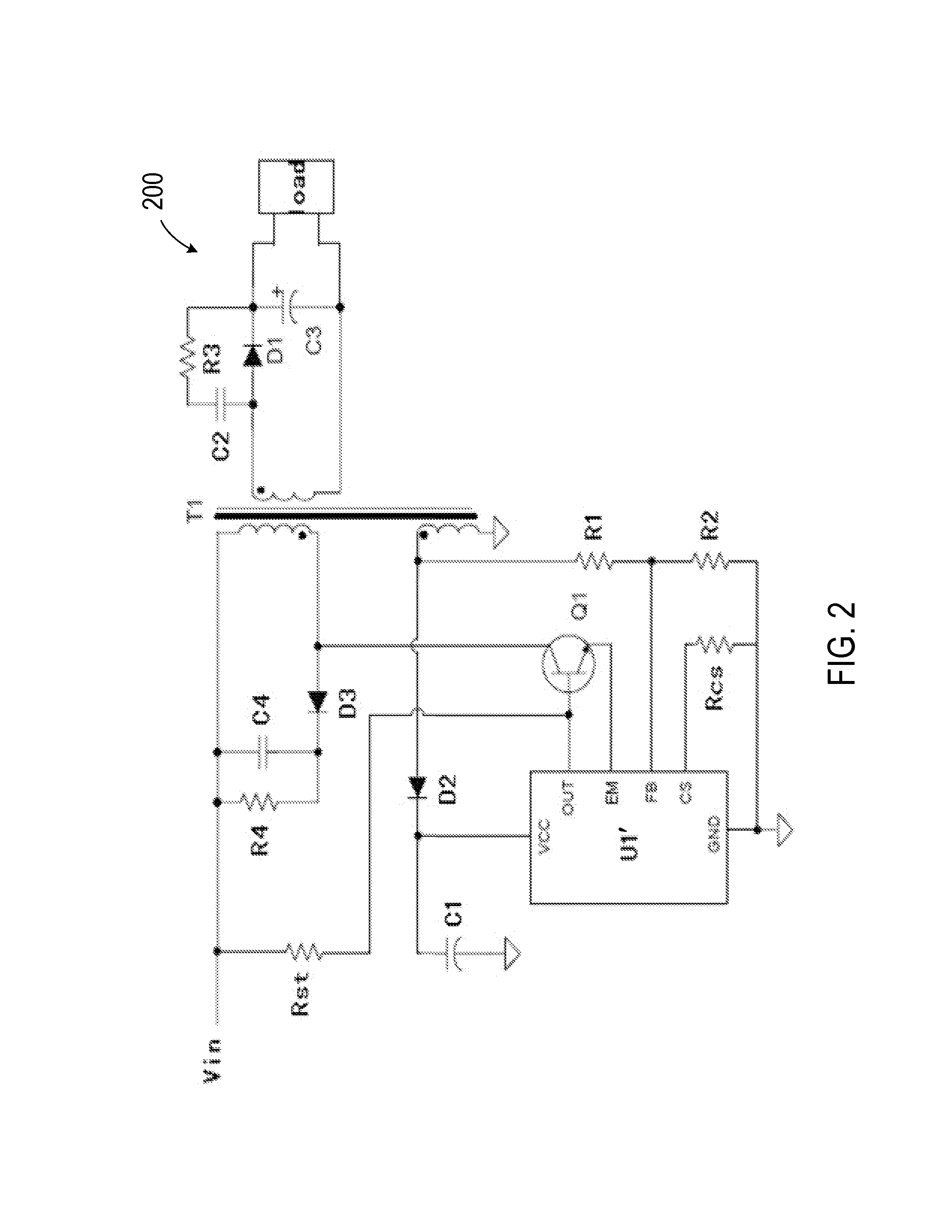
[0022]FIG. 1 illustrates a conventional flyback power supply circuit. As shown, power supply circuit 100 includes a primary-side controller U1. At startup, a controller supply voltage VCC capacitor C1 is charged by an input voltage Vin (from an external power supply) through a startup resistor Rst. When VCC reaches a turn-on voltage of primary-side controller U1, the primary controller U1 begins normal operation and outputs a switch control signal to drive an external power switch Q1. Diode D3, capacitor C4, and resistor R4 together form an RCD buffer circuit to reduce the transformer T1 leakage induced voltage spikes, to prevent breakdown and damage of power switch Q1. A resistor Rcs is in series connection with the emitter of power switch Q1 and is used for controlling transformer T1 primary inductor peak current, thus the maximum output power in the circuit. Capacitor C2 and resistor R3 form a buffer to remove the oscillation caused when the rectifier diode D1 is turned off. The ...


PUM


Abstract

A control circuit for a switch mode power supply (SMPS) includes a power switch for coupling to a primary winding of the power supply and a startup resistor coupled to an external input voltage and to a control terminal of the power switch. The control circuit also includes a controller. During startup, the controller is configured to cause the power switch to amplify a startup current from an external input voltage through the startup resistor and provide a startup power to the controller. During normal operation, the controller is configured to provide a power switch control signal to turn on and off the power switch for controlling a current flow in the primary winding and regulating an output of the power supply. The controller is configured to provide a current signal for driving an NPN power switch and to provide a voltage signal for driving an NMOS power switch.

Description

CROSS-REFERENCES TO RELATED APPLICATIONS[0001]This application claims priority to Chinese Patent Application No. 201210313484.6, filed Aug. 29, 2012, which claims priority to Chinese Patent Application No. 201110251283.3, filed Aug. 29, 2011, both of which are commonly owned and incorporated by reference herein.BACKGROUND OF THE INVENTION[0002]The present invention relates generally to the field of switch mode power supply (SMPS). More particularly, the present invention relates to power supply control circuits that have a fast startup time.[0003]In 1955, an American G. H. Roger invented the self-oscillation push-pull transistor single transformer DC-DC converter, which was the beginning of high-frequency switching conversion control circuit. In 1957, Jensen invented the self-oscillating push-pull dual transformers. In 1964 U.S. scientists proposed the abolition of frequency transformer series switching power supply, which pointed to a fundamental way of decreasing the size and weig...

Claims


Application Information

Patent Timeline
Patent Type & Authority Applications(United States)
IPC IPC(8): H02M1/36
CPCH02M1/36H02M3/33523
Inventor ZHANG, MEILINGGAO, XIAORUCHEN, CHAO
Owner BCD SEMICON MFG
Why Eureka
Try Eureka