Medical imaging device for providing an image representation supporting in positioning an intervention device

Active Publication Date: 2013-12-26
KONINKLJIJKE PHILIPS NV
View PDF23 Cites 17 Cited by
  • Summary
  • Abstract
  • Description
  • Claims
  • Application Information

AI Technical Summary

Benefits of technology

The proposed medical imaging device helps a surgeon to correctly position an intervention device while reducing the X-ray dose transmitted through the patient. It achieves this by continuously tracking the location of the intervention device and adjusting the settings of a collimator device accordingly to acquire live anatomy images only in a restricted area adjacent to the current location of the intervention device. This results in a significant reduction in the overall X-ray dose and restores the occluded anatomy background with pre-life images, possibly richer content previously acquired and possibly acquired in diagnostic conditions.

Problems solved by technology

Furthermore, X-ray fluoroscopy images may suffer from a poor contrast such that the patient's anatomy may be difficult to observe in such fluoroscopy images and it may be difficult to determine where the intervention device is positioned relative to the patient's anatomy.

Method used


Image

  • Medical imaging device for providing an image representation supporting in positioning an intervention device
  • Medical imaging device for providing an image representation supporting in positioning an intervention device
  • Medical imaging device for providing an image representation supporting in positioning an intervention device

Examples


Embodiment Construction

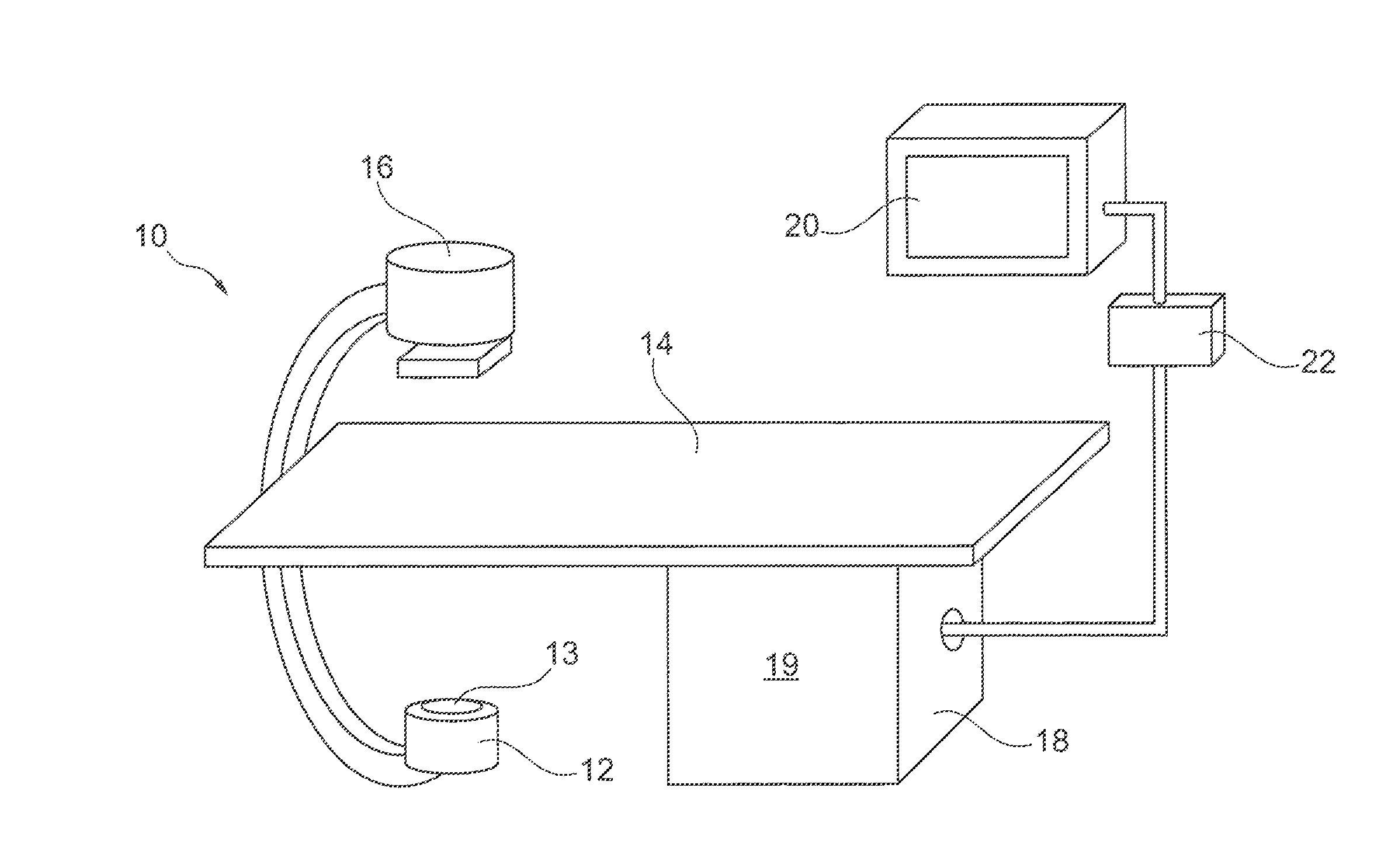
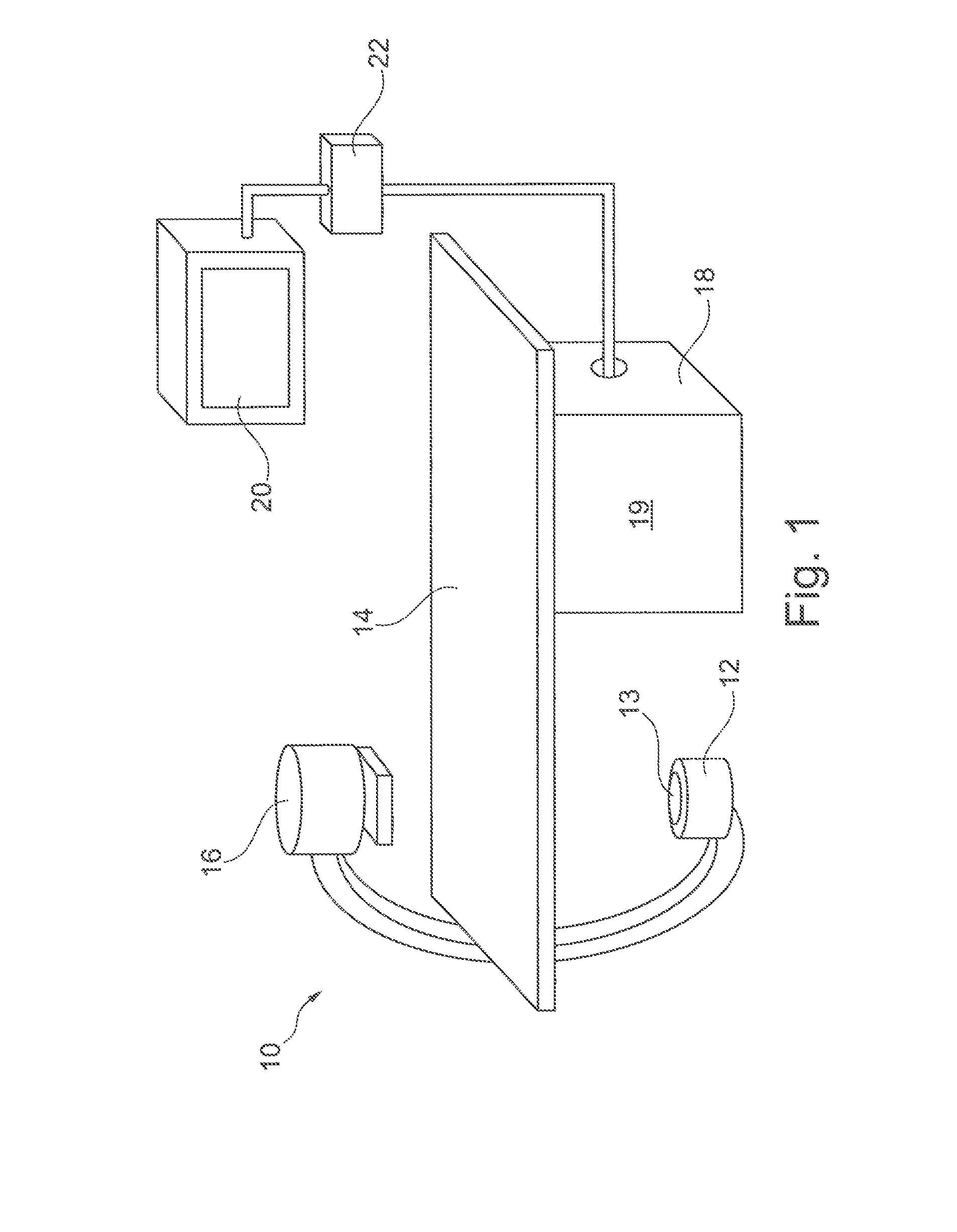
[0031]FIG. 1 schematically shows an X-ray medical imaging system 10 which may be used during an intervention procedure to provide an image representation thereby supporting a surgeon in positioning an intervention device within a patient in accordance with an embodiment of the present invention.

[0032]The imaging system 10 comprises an X-ray image acquisition device with an X-ray source 12 provided to generate X-ray radiation. The X-ray source 12 comprises a collimator 13 including shutters and wedges (not shown) in order to collimate the X-radiation onto a region of interest. A table 14 is provided to receive a patient to be examined. Furthermore, an X-ray image detection module 16 is located opposite to the X-ray source 12. During an imaging procedure, the patient is located on the table 14, i.e. between the X-ray source 12 and the detection module 16. X-rays are emitted by the X-ray source 12 and transmitted through the patient before being detected by the detection module 16.

[003...


PUM


Abstract

A medical imaging device and a method for providing an image representation supporting positioning of an intervention device such as a wire tip (4) in a region of interest during an intervention is proposed. Therein, the following process steps are to be performed: (S1) acquiring a pre-live anatomy image (1) including a region of interest; (S2) acquiring a live anatomy image using a live image acquisition device comprising an adjustable collimator device; (S3) identifying a location (5) of the intervention device (4) within the live anatomy image; (S4) adjusting settings of the collimator device based on the identified location of the intervention device for subsequently acquiring a further live anatomy image representing the region of interest using the live image acquisition device with the collimator device being in the adjusted settings; and providing (S5) the image representation by merging information from the live anatomy image into the pre-live anatomy image. Thereby, the intervention device may be continuously tracked and the collimator device may restrict a field of view to a location of the intervention device thereby significantly reducing an applied X-ray dose. Background anatomical information may be introduced into the final image representation using the pre-live anatomy image possibly having a higher image contrast than the live anatomy images.

Description

FIELD OF THE INVENTION[0001]The present invention relates to a medical imaging device which may be used for providing an image representation supporting in positioning of an intervention device in a region of interest during a medical intervention procedure. Furthermore, the present invention relates to a medical imaging system, a medical imaging method, a computer program and a computer-readable medium, all of which are adapted for providing an image representation which may be used in supporting for example a surgeon during positioning of a medical intervention device.BACKGROUND OF THE INVENTION[0002]During medical intervention procedures one or more intervention devices may have to be accurately positioned within a region of interest within a patient. For example e.g. during a cardiac catheterization a wire tip may have to be positioned at a precise location within a vessel system. In order to help a physician in such positioning, medical imaging devices are typically provided fo...

Claims


Application Information

Patent Timeline
IPC IPC(8): A61B5/00
CPCA61B5/0037A61B6/06A61B6/12A61B6/4441A61B6/481A61B6/487A61B6/503A61B6/504A61B6/5229A61B6/542A61B90/37
Inventor FLORENT, RAOULHOORNAERT, BART PIERRE ANTOINE JOZEFSTEGEHUIS, HERMAN
Owner KONINKLJIJKE PHILIPS NV
Why Eureka
Try Eureka