Hybrid drive of a motor vehicle

a hybrid drive and motor vehicle technology, applied in mechanical equipment, transportation and packaging, gear wheel sets, etc., can solve the problems of high manufacturing cost, large axial constructive length of manual transmission, and special design of manual transmission, so as to improve the smooth running of manual transmission, reduce the effect of gear wear and less wear

Inactive Publication Date: 2013-12-26
ZF FRIEDRICHSHAFEN AG
View PDF5 Cites 37 Cited by
  • Summary
  • Abstract
  • Description
  • Claims
  • Application Information

AI Technical Summary

Benefits of technology

[0022]In order to attain a higher variability in the design of the transmission ratios of the gear wheel sets with the manual transmission, it can be provided that at least one common fixed gear is formed by two gear wheel sets disposed in a common radial plane, as a stepped gear. As a result, additionally, a lower profile shift results in the gear engagement of the two associated idler gears, which leads to less wear to the gears and to an improved smooth running of the manual transmission.
[0023]For improving the operating properties of the hybrid drive, with an engagement of the internal combustion engine via a friction clutch, particularly for allowing shifts under load in the electric driving operation, the one input shaft can additionally be in drive connection with the rotor of a second electric machine, which is disposed at the end of this input shaft outside of the transmission and is preferably implemented as a starter generator.

Problems solved by technology

A disadvantage of the two named hybrid transmissions is however that the respective manual transmissions are special designs that are accordingly expensive to manufacture.
However, a disadvantage of the last named hybrid drive is that the axial constructive length of the manual transmission is relatively large due to the axial staggering of the gear wheel sets and the input constants.
This inevitably leads to axially large dimensions of the entire hybrid drive which makes the use thereof at least difficult in a motor vehicle, particularly with a front-transverse arrangement.

Method used


Image

  • Hybrid drive of a motor vehicle
  • Hybrid drive of a motor vehicle
  • Hybrid drive of a motor vehicle

Examples


Embodiment Construction

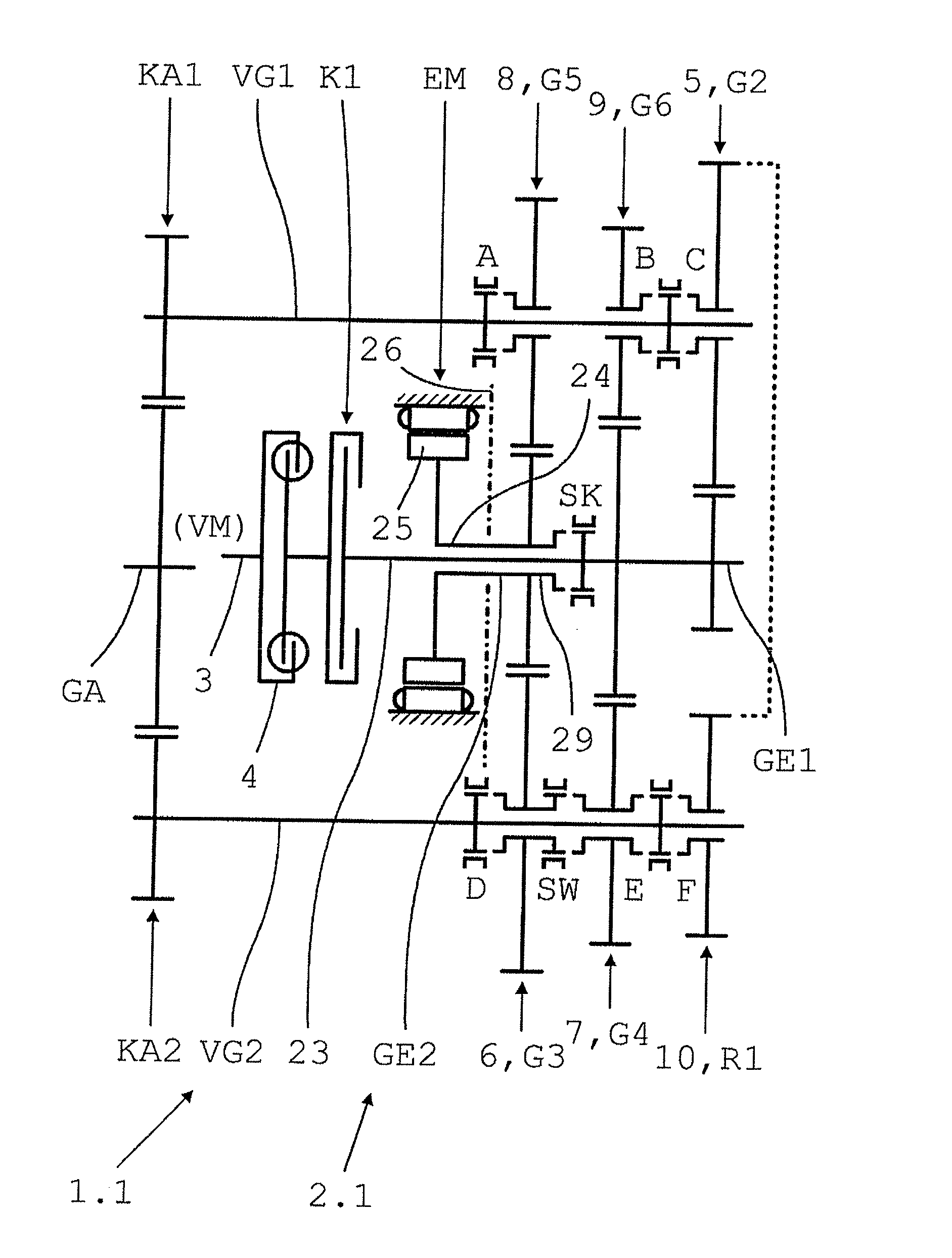
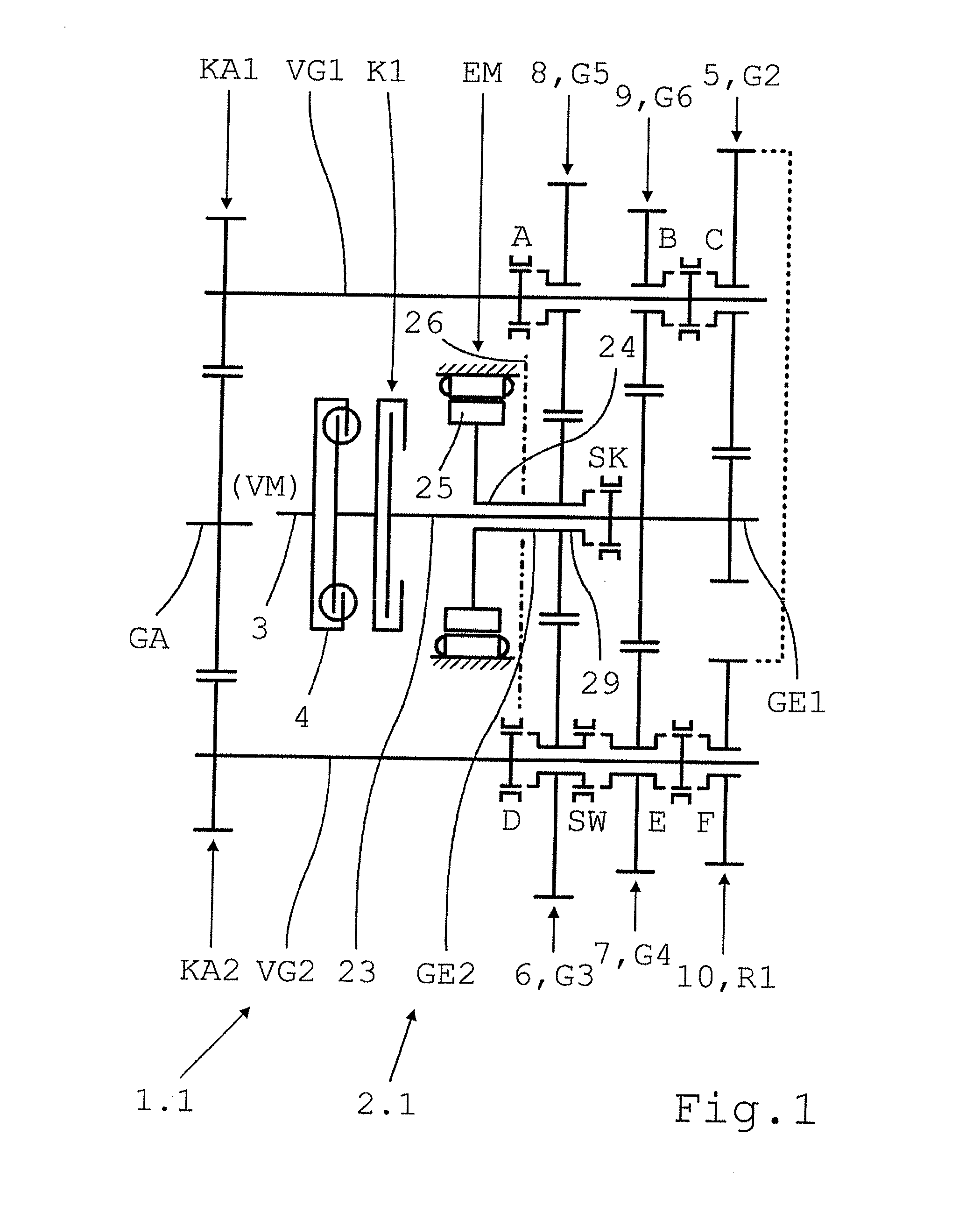
[0055]A schematic form of a double clutch transmission 2.0, known for example from the document DE 10 2007 049 271 A1, from which the following described manual transmissions 2.1 to 2.20 of the hybrid drive 1.1 to 1.8a according to the invention are derived, is shown in FIG. 21.

[0056]The double clutch transmission 2.0 has two coaxial input shafts GE1, GE2, two countershafts VG1, VG2 and one common output shaft GA. The first input shaft GE1 is disposed centrally within the second input shaft GE2, implemented as a hollow shaft. Both input shafts GE1, GE2, can each be connected on the input side, via an associated friction clutch K1 K2, to the drive shaft 3, provided with a torsional vibration damper 4, of an internal combustion engine VM, not shown in more detail. On the output side, both input shafts GE1, GE2 can be brought in drive connection, via a plurality of selectively shiftable gear wheel sets 5, 7, 9, 10, or 6, 8 with one of the two countershafts VG1, VG2, respectively. Both ...


PUM


Abstract

A hybrid drive of a motor vehicle having an automated manual transmission with two coaxial input shafts and a common output shaft. The input shafts are respectively driven by an engine and an electric machine and can couple the output shaft via respective groups of gearwheel sets. Each gearwheel set comprises a gear fixed to the associated input shaft and an idler gear supported by respective countershafts. At least two idler gears disposed on one of the two countershafts of two gearwheel sets, within the transmission, assigned to two different input shafts, can be coupled via a winding-path shift element, and the two output constants are disposed in a common radial plane by using a common output gear disposed on the output shaft.

Description

[0001]This application is a National Stage completion of PCT / EP2012 / 051632 filed Feb. 1, 2012, which claims priority from German patent application serail no. 10 2011 005 532.0 filed Mar. 15, 2011.FIELD OF THE INVENTION[0002]The invention relates to a hybrid drive of a motor vehicle, which has an automated manual transmission derived from a double clutch transmission with two coaxially disposed input shafts and a common output shaft, in which one of the input shafts of the hybrid drive can be connected to the drive shaft of an internal combustion engine and can be brought into drive connection with the output shaft via an associated first group of selectively shiftable gear wheel sets, and the other input shaft of the hybrid drive is in drive connection with the rotor of an electric machine that can be operated as a motor and as a generator, and can be brought into drive connection with the output shaft via an assigned second group of selectively shiftable gear wheel sets.BACKGROUND...

Claims


Application Information

Patent Timeline
Patent Type & Authority Applications(United States)
IPC IPC(8): F16H37/06
CPCF16H37/065Y10S903/902B60K6/48B60K6/547B60K2006/4825B60K2006/4841F16H3/006F16H3/093F16H2003/0826F16H2003/0935Y10T74/19014Y10T74/19233Y02T10/62
Inventor KALTENBACH, JOHANNESREISCH, MATTHIAS
Owner ZF FRIEDRICHSHAFEN AG
Why Eureka
Try Eureka